Multichannel Systems TC01-2 Manual User Manual
Page 12
Temperature Controller TC01/02 Manual
8
3.2 Setting Up and Connecting the TC01/02
Provide a power supply in the immediate vicinity of the installation site.
1. Place the TC01/02 on a dry and stable surface, where the air can circulate freely and the device
is not exposed to direct sunlight.
2. Plug the external power supply cable into the supply power input socket on the rear panel
of the TC01/02.
3. Connect the external power supply to the power outlet.
4. Optional, for recording temperature curves or remote control: Connect the USB cable
to a free USB port of the data acquisition computer.
5. Connect the TC01/02 to the heating element. Use the cable that is delivered with the heating
system or use a custom cable. The cable is plugged into the female D-Sub9 socket. (CH1 for
channel 1, CH2 for channel 2, if you have a TC02) See also chapter "D-Sub9 Pin Assignment"
in the Appendix.
3.3 Operating the TC01/02
3.3.1 Starting
the
TC01/02
All functions are set in the menu of the TC01/02, including switching the TC01/02 on and off.
If the TC01/02 is switched off, it goes into standby mode. The instrument and display are only
switched off completely when the TC01/02 is disconnected from the power supply. Most of the
power consumption of 6 W in standby mode is used by the power supply unit.
In the main menu on the display, select On / Off.
The TC01/02 starts to control the temperature on the selected channels immediately.
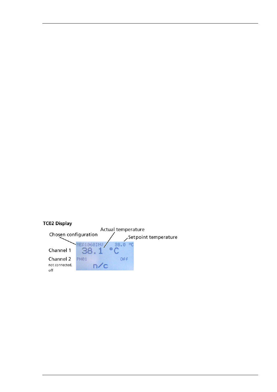
If the TC01/02 is connected properly, the actual temperature and the setpoint temperature
are displayed in the Temperature Control view.