3 pin layout – Multichannel Systems USB-ME64-128-256-Systems Manual User Manual
Page 29
Index
25
6.3
Pin Layout
Analog IN
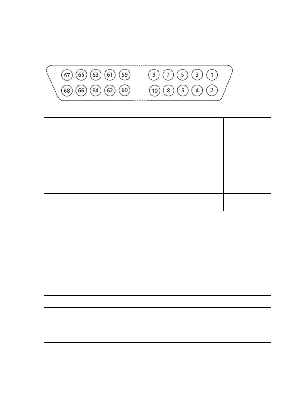
Pin Layout 68-Pin MCS Standard Connector
A
B
C
D
Pin 1
GNDP (power
ground)
GNDP
GNDP
GNDP
Pin 2
GNDS (signal
ground)
GNDS
GNDS
GNDS
Pin 3 - 66 Channels
1 - 64
65 - 128
129 - 192
193 - 256
Pin 67 Pos.
voltage
supply
Pos. voltage
supply
Pos. voltage
supply
Pos. voltage
supply
Pin 68 Neg.
voltage
supply
Neg. voltage
supply
Neg. voltage
supply
Neg. voltage
supply
Galvanically isolated voltage supply and ground. Pin 1, 67, and 68 are connected to the external
power supply, for example, PS40W.
Additional ANALOG IN
Please note that channels 253 to 256 are not used for recording analog data from MEA amplifier.
The 68-pin MCS Standard Connector has 64 possible channels for recording, but MEA amplifier
only has 60 channels for recording data. That is why channel 253 to 256 are diverged from
68-pin MCS Standard Connector D at the front panel and connected to the Analog 1 to 4
at the rear panel. These channels are used for the additional analog inputs of the USB-ME256.
Analog 1 Channel
253
Connector D, Pin 63
Analog 2 Channel
254
Connector D, Pin 64
Analog 3 Channel
255
Connector D, Pin 65
Analog 4 Channel
256
Connector D, Pin 66