Removal from flow meter, Moisture protection, About explosion proof installations – Max Machinery Explosion Proof Install User Manual
Page 2: Electrical installation
33A
Healdsburg Avenue
Healdsburg,
CA 95448
T
+ 1 707.433.2662
F
+ 1 707.433.1818
Max Machinery, Inc.
maxmachinery.com
EXInstallEnglish_001Q2.pdf • Rev2 • © 08/14/2013 Max Machinery, Inc.
`
Removal from Flow Meter
Note: the transmitter does not need to be removed from the flow meter for any field servicing or adjustments. Normally,
the flow meter and transmitter are shipped back to the factory for calibration as a unit.
1. Remove the locking screw at the edge of the lid and then remove the cap using a 3/8” socket drive.
2. Disconnect wires at the terminal block and remove wiring conduit from transmitter.
3. Locate the locking set screw below the conduit hole and remove it. Rotate the outer housing clockwise until the screw
hole lines up with a hole in the inner housing. (Inserting an Allen key into the threaded hole while rotating the housing
can help in finding the point of alignment.) Now re-insert the set screw and hand-tighten it. This will lock the inner and
outer housing together.
4. Unscrew the transmitter, using a strap wrench if necessary.
Moisture Protection
The housing is a liquid and vapor-tight enclosure certified to IP66. There is an O-ring seal at the lid of the housing — the
seal needs to be fully seated to provide moisture protection and achieve flameproof specifications.
About Explosion proof installations
For the Model EX295 and EX296 to fully adhere to the HazLoc certifications, the wiring must meet the appropriate
codes. (Use of a wire conduit does not make the installation explosion proof – read below.) The transmitters which are
certified for use in hazardous locations require the use of a 1/2” NPT hazardous location rated conduit fitting. The
wiring conduit must be sealed with a conduit stop within 18” of the device. If you choose to use exposed cables, cable
seals must be used with sealing fittings and the wiring must be an approved armored cable. (For detailed information on
the joint constructions used to achieve a flame proof housing, please contact Max Machinery.)
Electrical Installation
The transmitter includes a wiring pigtail and 2 part connector - use of the pigtail is optional and direct wiring to the
PCA is recommended if the circuit board is accessible. Use wiring that is between 20 and 28 gauge and rated to at least
5°C above the maximum ambient temperature, and rated to at least 80% of the maximum fluid temperature. Cut back
the cable bundles’ outer sheath several inches to make it easier to coil the wire loop inside the housing. The pigtail
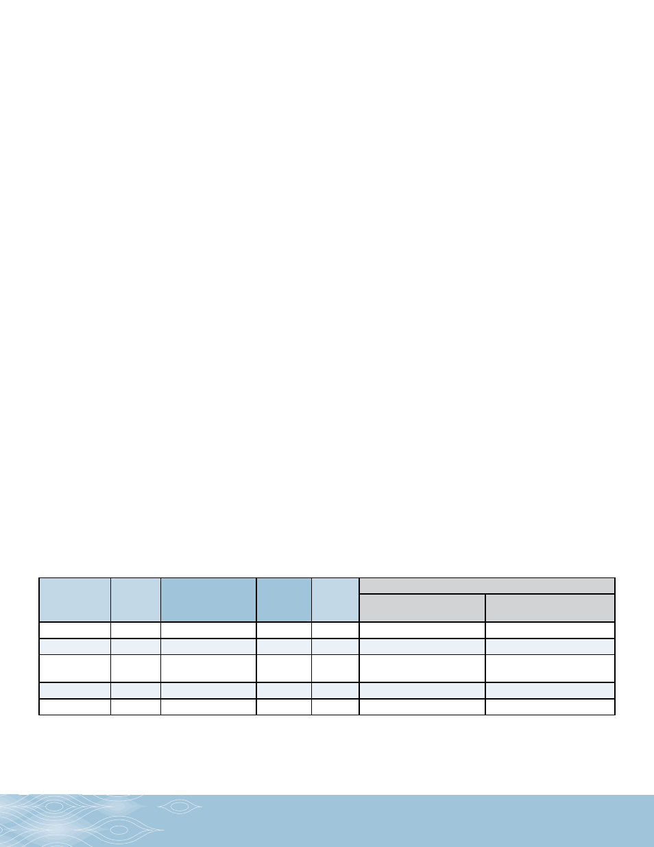
connector’s terminals correspond to the terminal block on the PCA. Refer to the diagram below for wire number and
functions.
* Consult Electrical Requirements Table
Pulse Output
Wiring
Pulse
PCB
Label
Analog Output
Wiring
Analog
PCB
Label
Wiring
Adaptor
Pin #
Two Part Transmitter Wiring
Ex-Proof Sender
(Example: EX29x-051-000)
Remote Receiver
(Example: EX296-x8x-xxx)
Power *
V+
Power
V+
1
Case
Case
Common
Com
Common
Com
2
5V
5V
Signal
Output
PhA
Signal Output (+)
Sig
3
Ra
Ra
(Quad only)
PhB
Signal Output (-)
Ret
4
Rb
Rb
Case Ground
Case
Case Ground
Case
5
Com
Com