Db - 624 lightbar dimmer – Lightronics DB624 User Manual
Page 6
Page
6
of
9
DB - 624 LIGHTBAR DIMMER
Version: 0.6
OWNERS MANUAL
09/19/2008
www.lightronics.com
Lightronics Inc
509 Central Drive Virginia Beach, VA 23454
Tel 757 486 3588
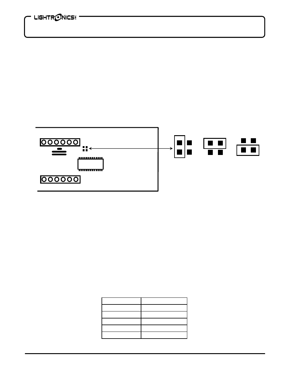
PHASE SENSING JUMPER
There is a small black jumper block located on the back of the control circuit board which must be set to
correspond to either single phase, or 3 phase AC input power. Install the jumper according to the power at your
facility using the diagram below. The positions are shown below and are marked on the circuit board. The control
circuit board is mounted in the inside of the main control panel which is the front center panel on the unit. The 3
Phase Reverse setting is provided only to correct “out of sequence” power input connections. Also see the
section “Three Phase Power Connections for more information concerning the 3 Phase Reverse setting.
The DB-624 is usually shipped from the factory set for 3 Phase Normal operation.
Disconnect or turn off power to the unit before changing jumper settings
CHANNEL OUTPUT CONNECTIONS (LAMP LOAD CONNECTIONS)
Dimmer channel output connectors are on the face of the unit. Two connections are available for each channel
(the optional twist-lock panels have one connection per channel). The numbering for the channels is shown on
the unit center faceplate. The maximum load for each channel is 2400 Watts or 20 Amps.
CONTROL SIGNAL
The DB-624 is intended to be used with a control console which has been UL-508 Certified or uses only Low
Voltage power. This ensures that any cabling or other power anomalies will not damage the DB-624 or your
console.
Connect a Lightronics or other USITT DMX-512 compatible control console to the DB-624 using the MALE 5 pin
XLR connector located on the center faceplate of the unit. This connector is marked DMX IN. The FEMALE 5 pin
XLR connector is provided so you can connect multiple dimmers as a system. This connector is marked DMX
OUT and will pass the DMX signal through to additional dimmers on a chain. Connector wiring information is
given below.
PIN NUMBER
SIGNAL NAME
1 DMX
Common
2 DMX
Data
-
3
DMX data +
4 Not
Used
5 Not
Used
Control Circuit Board - Rear View
CIRCUIT BOARD
JB1
Single
Phase
3 Phase
Normal
3 Phase
Reverse
PHASE SELECTION
1PN 3PN 3PR