Db - 624 lightbar dimmer – Lightronics DB624 User Manual
Page 5
Page
5
of
9
DB - 624 LIGHTBAR DIMMER
Version: 0.6
OWNERS MANUAL
09/19/2008
www.lightronics.com
Lightronics Inc
509 Central Drive Virginia Beach, VA 23454
Tel 757 486 3588
SINGLE PHASE POWER CONNECTIONS
The DB-624 may be field converted to accommodate a SINGLE PHASE 120/240 power service. Consult the
applicable electrical codes for your location for exact wire specifications. The unit must be powered from a circuit
providing a minimum of 60 Amps per line (2 pole 60 Amp circuit breaker). The minimum wire size is AWG#6.
Wire may be either stranded or solid. The terminals are intended for copper wire only.
1 Remove the access cover at the end of the unit.
2 Connect the 2 "HOT" power input wires to the
L1 and L3 terminals.
Note that the terminal marked L2 is not used for single phase operation.
3 Connect the neutral wire to the terminal marked
N.
4 Connect a ground wire to the CHASSIS GROUND terminal marked
G.
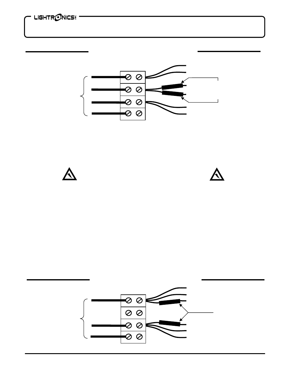
There are two blue wires in the
L2 terminal on the opposite side of the power input terminal strip. These wires
have color coded shrink tubing markers on them. One of them is marked with BLACK. The other is marked with
RED.
5 Move the BLUE wire with the BLACK marker from the
L2 terminal to the L1 terminal.
6 Move the BLUE wire with the RED marker from the
L2 terminal to the L3 terminal.
A diagram of single phase power connections is shown below :
L1
SINGLE PHASE
120/240VAC
60A EACH LINE
L2 NOT USED
L3
NEUT
BLACK
RED
BLACK
BLACK
BLUE
RED
RED
BLUE
COLOR
CODED
SHRINK
TUBING
BLACK
3 PHASE
120/208VAC
40A EACH/LINE
L1
L2
L3
NEUT
COLOR
CODED
SHRINK
TUBING
BLACK
BLUE
BLUE
RED
RED
BLACK
RED
THREE PHASE POWER INPUT CONNECTIONS
SINGLE PHASE POWER INPUT CONNECTIONS
Factory Supplied Configuration
MAKE CERTAIN THAT THE INPUT POWER SOURCE IS
DE-ENERGIZED BEFORE MAKING CONNECTIONS.