Rd - 122 rack mount dimmer, Page 3 of 14 – Lightronics RD122 User Manual
Page 3
Page 3 of 14
RD - 122 RACK MOUNT DIMMER
Version 1.3
OWNERS MANUAL
03/09/2011
www.lightronics.com
Lightronics Inc.
509 Central Drive, Virginia Beach, VA 23454
(757) 486-3588
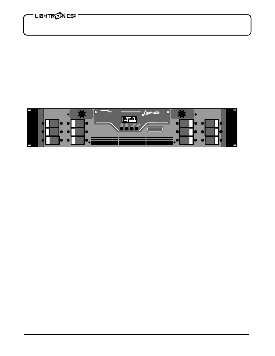
UNIT DESCRIPTION AND FUNCTIONS
The RD-122 is a 28,800 Watt, 12 channel, rack mountable lighting dimmer. Each of the channels has a capacity
of 2400 Watts. It is controlled via low voltage signals which may be LMX-128 (3 wire multiplex), or USITT DMX-
512. The unit is fan cooled. Channels may be independently assigned from the unit. The unit is over
temperature and over voltage protected and has a magnetic circuit breaker for each channel. There are several
options for channel output connection panels. Options include: Edison plug, External Terminal Strip, Patch
Panel, and Socapex Connector panel. The RD-122 has several stand alone functions which enable it to operate
without a control console. These functions include a storable scene which may be activated by an external switch
closure, a programmable chaser, and 7 factory set chase patterns.
POWER REQUIREMENTS
Each RD-122 requires both hots from a SINGLE PHASE 120/240 VOLT AC or TWO PHASES OF A THREE
PHASE 120/208 VOLT AC service. The neutral conductor is shared by two hots so it is important that the two
hots used are of different phases. EACH PHASE must be capable of providing 120 AMPS. Line frequency is
typically 60HZ. A 50HZ model is available for export. Refer to the dimmer electrical rating markings to determine
the operating frequency. One or more RD-122 dimmers may be installed into a standard 19" equipment rack with
provisions for connection to an appropriate electrical service in accordance with the National Electrical Code.
INSTALLATION
PLACEMENT
The RD-122 is designed to be mounted in a standard 19" equipment rack using the four mounting holes in the
face plate of the dimmer. If the dimming system will be used for touring shows, it is recommended that you
provide additional support for the rear of the unit. The dimmer is fan cooled and requires no space between units
when multiple dimmers are used. Air enters the dimmer through slots on the side and exits through holes in the
bottom of the face plate. Make certain these ventilation holes are not obstructed. Do not place the RD-122 where
it will be exposed to moisture or excessive heat. The RD-122 is intended for INDOOR USE ONLY.
POWER CONNECTIONS
Make certain power is removed from the circuits before you begin installation of the dimmer. Consult your
local electrical codes to determine the proper wire type and wiring methods for your installation.
Power enters the RD-122 through a knockout sized hole at the rear of the unit. Remove the top cover and install
an appropriate cable clamp in the knockout hole. Pass the power cables through the hole. Behind the hole is a
terminal block with three lugs. The connections labeled "H1" and "H2" are the line or "hots". The center
connection labeled "N" is the neutral. There is an additional lug labeled "G" to the right of the terminal block. This
is for connecting the unit to earth ground. When connections are completed, reinstall the cover and tighten the
cable clamp.
D
12 X 2.4 KW
DMX / LMX
RD - 122
CAUTION
CAUTION
RISK
OF
FIRE
RISK
OF
FIRE
REPLACE
ONLY WITH
1/2 AMP, 250V
SLOW BLOW
FUSE
REPLACE
ONLY WITH
1/2 AMP, 250V
SLOW BLOW
FUSE
ME
NU
SE
LE
CT
A
B
C
PHASE
A
PHASE
B
D
E
F
G
H
FUSE
FUSE
I
J
K
L