Liquid Controls Back Check Valves A2885 & A2883 LPG, A2882 Refined Fuels User Manual
Page 4
4
a2885 & a2883 (lPG)
a2885 & a2883 back Check Valves
reTrofIT InsTallaTIons
Depending on the existing configuration, adding an
A2885 or A2883 Back Check Valve may require
modification of the inlet piping.
After the internal pressure is relieved from the system,
the inlet line can be disconnected from the inlet side of
the strainer assembly. The valve and flange assembly
can then be connected to the inlet side of the strainer.
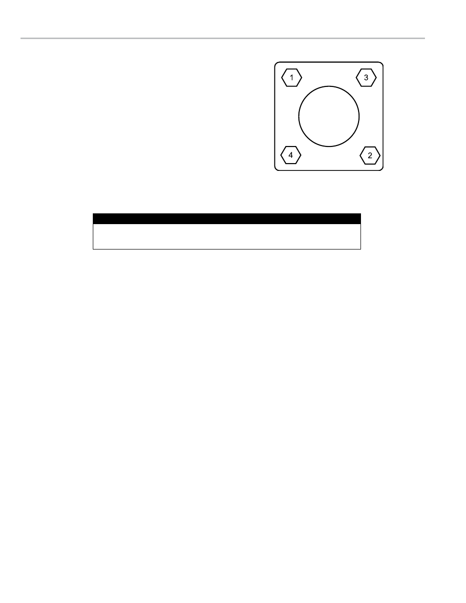
Use the four bolts and washers provided to fasten the
valve/flange assembly to the strainer as shown on Page
3. Tighten the bolts in a crossing pattern as shown to the
right. Once the valve/flange assembly is secure, the inlet
line may be reconnected to the flange. The flange fitting
is 2” NPT.
dIsasseMbly
1. Remove the valve from the line by removing the four
screws (Item 3) and washers (Item 4) that hold it in place.
2. Using a tire valve stem changer, remove the relief valve
(Item 920) from the valve stem (Item 265).
3. From the inlet side of the valve, unscrew the valve stem
(Item 265) from the valve nut (Item 875).
4. Remove the valve nut (Item 875) by pressing down on
the spring holder (Item 382). The spring should be held
down with a press. Lift the valve nut out of position. The
spring holder and lock washer can now be removed from
the housing.
5. Remove the O-Ring retainer (Item 452), O-Ring (Item
470), piston (Item 133), O-Ring (Item 471), and spacer
(Item 472), lifting by the threaded end of the valve stem
(Item 265).
6. Remove the O-Ring retainer (Item 452) and O-Ring (Item
471) from the stem.
7. Remove the O-Ring (Item 471) and the piston (Item 133)
from the stem.
8. Replace components if necessary and reassemble. The
bushing (Item 485) is pressed in place and need not be
removed.
Bolt Tightening Pattern
reasseMbly
1. Place the piston (Item 133) on the valve stem (Item 265),
with the raised rim pointing upwards.
2. Place the spacer (Item 472) and O-Ring (Item 471) on
the piston (Item 133)
3. Place the O-Ring (Item 470) on the retainer (Item 452)
and place it over the piston (Item 133) with the O-Ring
downward.
4. Place a self locking nut (Item 875) on the valve stem and
tighten. Place a second self locking nut (Item 875) on the
valve stem and tighten.
5. Insert this assembly into the housing (Item 110) from the
outlet side.
6. Place the compression spring (Item 595) over the valve
stem (Item 265).
7. Insert the Teflon bearing (Item 486) into the valve spring
holder (Item 382).
8. Place the spring holder (Item 382) on the housing (Item
110) and compress the spring inward. A press should be
used to overcome the force of the spring.
9. Secure the spring holder with the spiral retaining ring
(Item 393).
10. Screw the pressure relief valve (Item 920) into the valve
stem (Item 265) using a tire valve stem changer.
11. Place the O-Ring (Item 473) in the groove on the outlet
side of the housing assembly (Item 110).
The back check valve is now ready to be reinstalled using the
four screws (Item 3) and washers (item 4).
Refer to the illustrated parts breakdown on Page 6 for Item Numbers referenced in these
instructions. Item Numbers appear in circles in the drawing.
Item Numbers