Receiver installation, Operating instructions – Lectrosonics SIXPACK User Manual
Page 7
Multi-Channel Wireless System
Receiver Installation
The SIXPACK system is designed to contain up to six
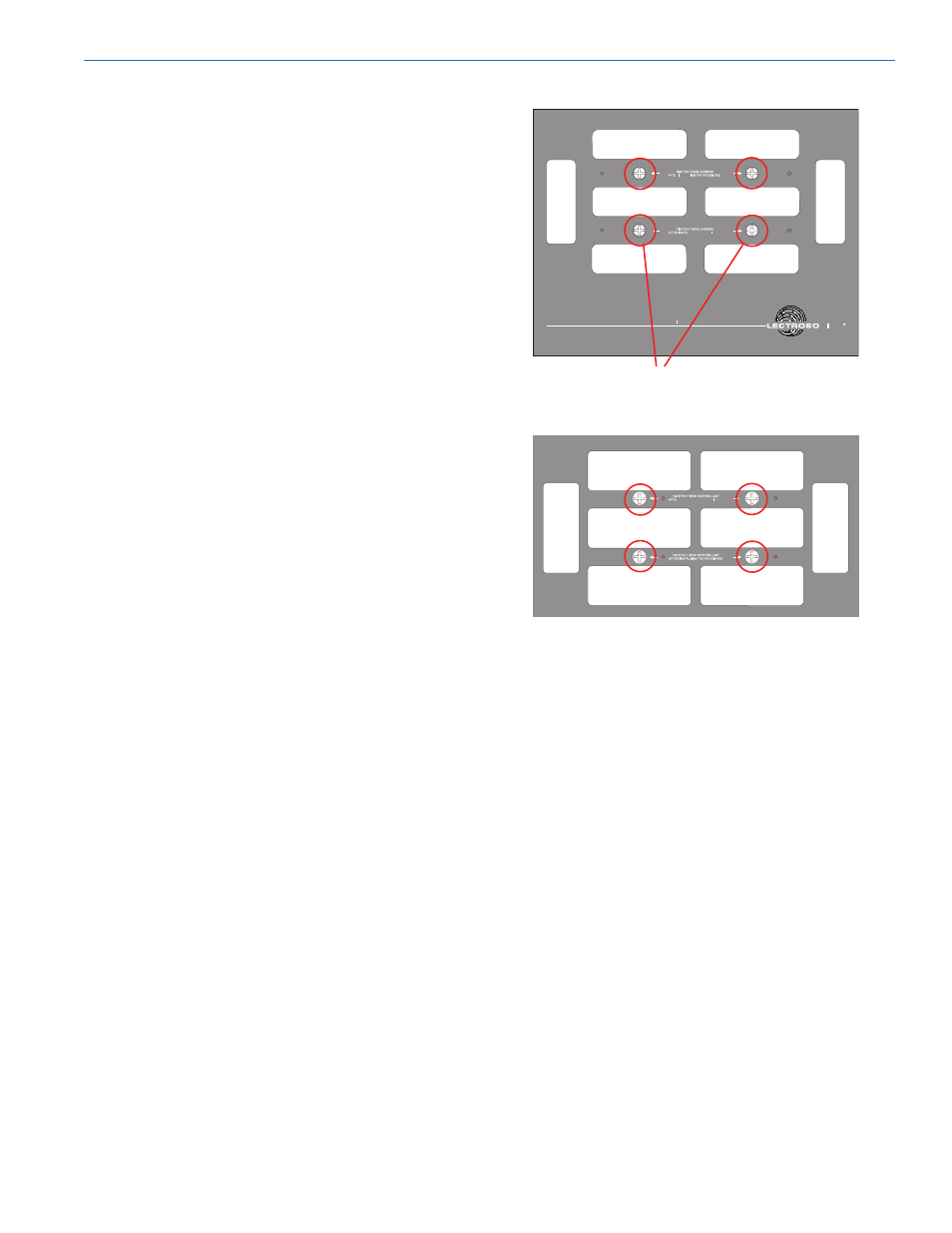
receivers. Installation of these receivers is quite simple.
First, loosen but do not remove, the four large counter
sunk phillips head screws in the front panel and the
four in the rear panel of the housing. Insert the receiv
ers, front panel first (the end with the antenna connec
tion) through the rear panel. Seat the front end of the
receiver into the recessed lip of the front panel. Repeat
this for each receiver to be installed. After all receivers
are in place, hold them in position and tighten the front
panel screws first. These screws should be fairly snug
but excessive force should be avoided and is unneces
sary as you are compressing a natural rubber tension
tube. Tighten the rear panel screws last. Press on the
front of each receiver to be certain that the receivers
are held securely.
At the front panel, attach the antenna leads to each
receiver, making sure the BNC connector is securely
locked into place. Antenna leads serving empty slots
do not need to be terminated.
At the rear panel, insert the power connectors into the
power jack of each receiver. If using battery powered
receivers it is recommended that each receiver have a
fresh battery in place to serve as backup power in the
event that the internal battery pack or external power
source fails for any reason.
Operating Instructions
Turn the power switch on the master distribution mod
ule to EXT or EXT OR BAT and set the power switches
on the receivers to operate from external power. The
power indicators should light on all the receivers and
the distribution modules.
The EXT position will allow the SIXPACK SYSTEM to
operate ONLY on external power no matter what the
external voltage is. If the voltage of the external power
source (not the charger) drops below operational
levels, then the system may not operate. The EXT OR
BAT position allows use of an external power source
until that source drops below 9 volts, at which time a
relay switches automatically to the internal batteries.
The charger can be used to power the system from
an external AC source and charge the batteries at the
same time. The AC LED will light when external volt
age is present and the CHARGE LED will light when
the batteries are taking a charge.
After use, recharge the batteries immediately to
prolong their life. The system incorporates industrial
quality gel-cells which can be left on charge for 10
days at a time without damage. The charging circuitry
will automatically limit the current flow to the batteries.
There are no “memory” problems with these batteries,
however, it is best to never allow the batteries to sit idle
when they are discharged.
Charge after every use for
maximum battery life.
Loosen the 4 screws on the front and rear panels,
but do not remove them
, to remove the receivers.
Tighten the screws on the front panel FIRST when
installing the receivers.
The CHARGE LED will light up to indicate the batter
ies are charging and will go out when the batteries
are at full charge. The charge rate is up to 3.5 Amps
for about 3 hours falling to a rate of 1 Amp. When the
charge rate drops to 1 Amp, the green LED will reduce
brightness to 1/2 and the battery voltage will be 13.8V.
At approximately 16 hours, the unit will achieve full
charge. It may be left on charge for a few days without
damage although we do not recommend leaving the
system on charge continuously.
Important - this unit
will achieve an operational level of charge after 3
hours from a totally dead battery.
The red BAT LED will go out when voltage drops to
11.5 volts - approximately 10% battery capacity re
mains at that point.
External DC power is connected to the system through
the 4-pin XLR connector on the rear panel. Pin 1 is
negative or ground, pin 4 is positive. Polarity is noted
on the housing.
Rio Rancho, NM
7