Optimized architecture – Lectrosonics ASPEN User Manual
Page 4
Optimized Architecture
TM
The ideal structure for signal flow and functional blocks
through a system wide matrix is a direct path from inputs
to crosspoints to outputs, with no extra paths or taps
necessary to add signal processing. It must offer a full
capability of routing every audio input to any one or all
audio outputs without limitation. Every audio input should
have its own dedicated signal processing blocks present
at all times. Every audio output on any unit in the system
should have full access to any crosspoint in the matrix,
and have its own dedicated signal processing present
at all times. This ideal structure is fully realized in the
Optimized Architecture
TM
of ASPEN.
All available signal processing is enabled on every
input and output with no resource meter or “gas gauge.”
Signal processing blocks are configured in the optimal
sequence needed to ensure the highest signal to noise
ratio and lowest distortion. This architecture eliminates
the need to manually construct a drawing and connect
one processing block to the next one in the chain. Simply
enable a crosspoint and the connections are made.
Setup is straightforward and simple in spite of the im-
mense amount of processing available. Settings are
applied in real time as the system is operating without
the need to compile and download files to the hardware.
Once the setup is complete, it is saved to a preset in the
hardware and to a disk file for backup.
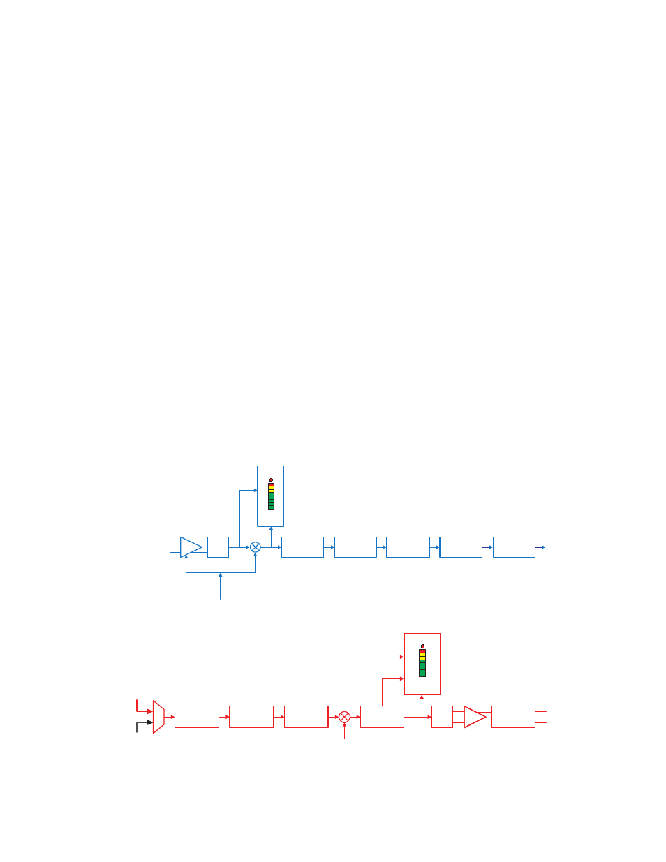
Input Processing
In addition to the delay, filters and compressor, there are
two special purpose processing blocks:
• NRF (noise reduction filter)
• ADFE (auto digital feedback eliminator)
NRF employs a proprietary noise reduction algorithm
on every input channel using a 1/3 octave analysis and
downward expansion. The amount of noise reduction ap-
plied to the signal at each input is adjustable from 6 dB
to 35 dB as needed for the signal conditions and to sat-
isfy individual preferences. The process is very effective,
with almost no audible artifacts at 18 dB or more. Higher
values are available for extremely poor conditions where
noise is extremely high and intelligibility is preferred at
the expense of subtle artifacts in the audio.
ADFE (auto digital feedback eliminator) is a notch filter-
ing process with static or dynamic behavior as defined
in the setup. Fixed notch filters can be configured as
needed for appropriate applications, and dynamic notch
filters can be defined to deal with changing conditions.
Output Processing
Each output channel can take its signal from the matrix
or from an internal signal generator. The generator can
deliver a variety of signal types for setup, diagnostics
and sound masking. The processing blocks on every out-
put are arranged in the optimal sequence used to feed
power amplifiers and recorders.
Audio
Input
ADC
Clip
Level
[dBu]
Delay
Noise
Reduction
Filter
ADFE
NRF
Tone Control
Compressor
To
AutoMix
Matrix
PreAmp (analog) Gain =
0, 8, 16, 24, 32, 40, 48, 56 dB
Digital Gain
Input Gain = 0, 1, ...60 dB
1. Premap Gain is selected to be the greatest available such that
PreAmp Gain <= Input Gain
2. Digital Gain = Input Gain – PreAmp Gain
Feedback
Eliminator
Input Signal Processing Blocks
48 Final
Mixes
M
u
x
Delay
Parametric
EQ
Compressor
Limiter
Comp/Lim
Level
[dBu]
DAC
Attenuation = 0, 20, 40 dB
Attenuator
Audio
Output
Channels
9 – 12 only
4 Internally
Generated
Signals
Output Gain [dB] = Off, -69,...0, 1,...20
Output Signal Processing Blocks