Scalability in the aspen matrix, Signal propagation in the aspen bus, Aspen 8x12 mixer signal flow – Lectrosonics ASPEN User Manual
Page 3: Aspen input only signal flow
Scalability in the ASPEN Matrix
Each 8x12 mixer board provides 8 physical inputs, 12
physical outputs and access to the audio and data from
the 48 final mixes in the ASPEN bus. Four virtual inputs
are provided in any system configuration to feed signals
from a built-in signal generator for setup, diagnostics and
sound masking.
As multiple units are stacked, the size of the matrix
grows accordingly. For example, a 16 input 2RU mixer
model actually has 20 inputs when the virtual inputs are
included. The matrix then consists of 960 fully functional
crosspoints (20x48). As more inputs are added, the size
of the matrix continues to increase without limitation.
Even with hundreds of inputs, every input can feed any
one or all of the 48 outputs, with full signal processing
available on every input and output.
Audio
Inputs
(8)
ADC
InProc
AutoMix
Matrix
M
S
Gain
Master
/
Slave
(Automatically Detected)
SubMix
Outputs
SubMix
Inputs
Virtual
Inputs
Physical
Inputs
SigGen
(4)
Lower ASPEN
Transceiver
Upper ASPEN Transceiver
M
u
x
M
u
x
OutProc
OutProc
DAC
DAC
Audio
Outputs
(12)
Monitor
Output
Final Mixes (48)
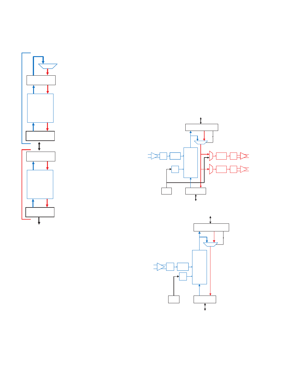
ASPEN 8X12 Mixer Signal Flow
Final
Mixes
Audio
Inputs (16)
ADC
InProc
AutoMix
Matrix
M
S
Master
/
Slave
(Automatically
Detected)
SubMix
Outputs
SubMix
Inputs
Physical
Inputs
Lower ASPEN
Transceiver
Upper ASPEN Transceiver
SigGen
Gain
Virtual
Inputs
ASPEN Input Only Signal Flow
Signal Propagation in the ASPEN Bus
The ASPEN bus provides a 1 Gbps throughput carrying
audio and data with a single CAT6 connection between
the units in a system.
When multiple units are
stacked, Master and Slave
units are automatically de-
tected and configured for the
correct signal flow.
Audio and data signals
propagate through submixes.
The lowermost slave in the
system generates a sub-
mix of signals from devices
connected to it and passes
the submix to the next slave
above it.
Each intermediate slave unit
adds to the submix from
the unit below it, updates
the submix and passes it
on to the unit above it. The
process continues through
all slave units in the system
with no limitation on the total
number of slave units that
can be used.
The Master unit gathers the
submix from the slave below
it, updates it with its own
signals and generates the
final mix. The final mix is
then back propagated to all
slave units below it to enable
system wide auto mixing and
control.
The audio output of all units
in the system is taken from
the 48 channel final mix.
This unique architecture allows a single computer or
network connection to the Master to have access to all
units in the stack.
M
S
Master
Automatically
Detected
CAT6 Cable
Lower ASPEN
Transceiver
Upper ASPEN
Transceiver
SubMix
Outputs
SubMix
Inputs
Final
Mix
Outputs
Final
Mix
Inputs
Lower ASPEN
Transceiver
Upper ASPEN
Transceiver
SubMix
Outputs
SubMix
Inputs
Final
Mix
Outputs
Final
Mix
Inputs
CAT6 Cable
Additional
Slaves
Master
Sla
ve
48 Final Mixes