Controls and functions – Lectrosonics UH110 User Manual
Page 4
CONTROLS AND FUNCTIONS
The UH110 may be used with a wide variety of microphones.
The 3-pin XLR connector on the UH110 allows the transmitter to
be used with any dynamic microphone, as well as many two wire
positive bias lavalier systems (such as those systems supplied
by Lectrosonics).
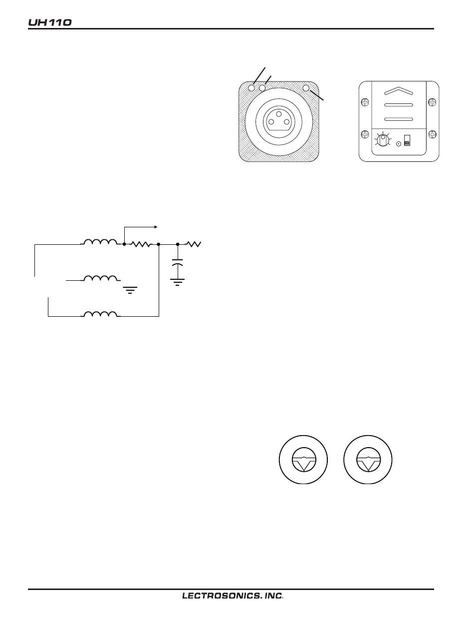
INPUT JACK
Standard 3-pin Switchcraft XLR type. Pin 2 is signal, pin 3 is a
floating signal ground, and pin 1 is case ground (see schematic
below). The UH110 is self-locking onto a standard microphone.
The XLR connector is permanently bonded to the metal collar,
and is not normally replaceable. The electret bias is 5 Volts at
1mA or less. The bias is connected in a “phantom” manner and
will not interfere with any standard balanced microphone. If
severe noise is experienced when the microphone is moved
with respect to the UH110, the cause is an unbalanced con
dition between pins 2 and 3 of the microphone.
To Mic
Preamp
1uh
1
2
3
1uh
1uh
1K
100
+5V
100uf
Input Jack Schematic
POWER SWITCH
Turns the battery power on and off.
POWER ON/OFF LED
Glows brightly when battery is good. A weak or dim LED means
that the battery is weak, and has about an hour of operation left.
If the LED fails to light, the battery should be replaced.
The POWER LED is connected to a precision battery test circuit
that continuously monitors battery voltage. The LED is at full
brightness with a new 9 Volt alkaline battery. As the battery
voltage drops during use, the LED brightness will also decrease.
After 5 hours the battery voltage will be about 7 Volts. The LED
will be completely extinguished. Since the internal circuits are all
tightly regulated and the RF output stage has a separate discrete
regulator, the transmitter will continue to operate to a battery
TOP VIEW
CONTROL PANEL
LIMIT LED
LEVEL LED
O N
O F F
L E V E L
BATTERY
POWER
LED
voltage of 6.5 Volts. From 6.5 Volts to 6 Volts, the transmitter will
still operate, but with degraded performance. Please note that a
weak battery will sometimes light the POWER LED immediately
after turn on, but soon will discharge to the point where the LED
will extinguish.
The combination of an accurate battery condition indicator and
regulation of all internal circuits guarantees much longer battery
life, as well as consistent performance versus battery life.
MODULATION LEDS: Indicate the proper setting of the MIC
LEVEL control.
LEVEL LED: Flickers or glows most of the time if the audio
volume is adequate for normal operation.
LIMIT LED: Lights up when the audio volume is high, indicating
that the signal level is being limited by the compressor. Optimum
signal-to-noise ratio is obtained when the limit LED lights occa
sionally.
MIC LEVEL: Used to adjust the audio input volume for the
proper modulation level. Rotate knob until the LEVEL LED
flickers when there is an input signal. The LIMIT LED should light
occasionally.
FREQUENCY ADJUST
These two rotary switches adjust the center frequency of the
carrier. The left switch is a coarse adjustment and the right
switch is the fine adjustment. Each transmitter is factory aligned
at the center of its operating range. The default position of the
frequency select switches is in the center of the transmitter’s
range.
0
1
2
3
4
5
6
7
8
9
A
B
C
D
E
F
0
1
2
3
4
5
6
7
8
9
A
B
C
D
E
F
Frequency select switches, default position (8,8)
4