General technical description, Uhf multi-frequency plug-on transmitter, General – Lectrosonics UH110 User Manual
Page 3: Dual band compandor, Pre-emphasis/de-emphasis, Long battery life, Frequency agility, Uh110 block diagram, Rio rancho, nm – usa 3
UHF Multi-frequency Plug-on Transmitter
GENERAL TECHNICAL DESCRIPTION
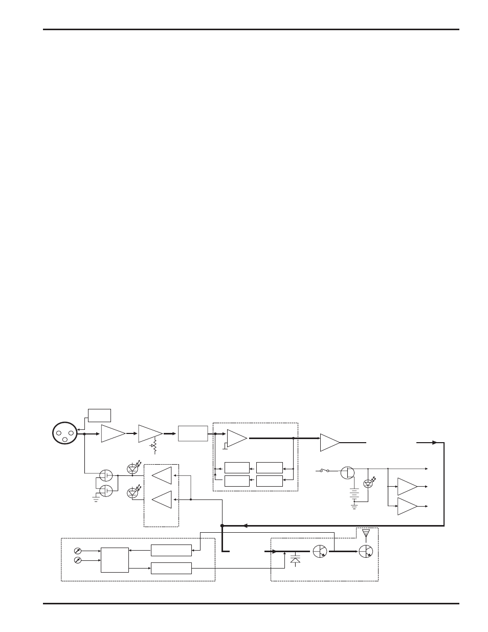
The UH110 transmitters are comprised of a number of functional
subsystems as shown in the block diagram below.
GENERAL
The 110 system uses 20kHz wide deviation for a high signal to
noise ratio. The transmitter circuits are all regulated to allow full
output power from the beginning (9 Volts) to the end (6.5 Volts) of
battery life. The input amplifier uses an ultra low noise op amp. It
is gain controlled with a wide range input compressor which
cleanly limits input signal peaks over 30dB above full modulation.
DUAL BAND COMPANDOR
Traditionally, compandors have been a source of distortion in
wireless microphone systems. The basic problem with conven
tional systems is that the attack and decay times are always a
compromise. If the time constants are fast, high frequency
transients will not be distorted, but this will cause low frequency
distortion. If the time constants are slower, low frequency audio
distortion will be low, but high frequency transients will then be
distorted. The 110 system introduces an entirely new approach
to solving this basic problem, called “dual-band companding.”
There are actually two separate compandors in the 110 system,
one for high frequencies and one for low frequencies. A cross
over network separates the frequency bands at 1kHz with a 6dB
per octave slope, followed by separate high and low frequency
compandors. The attack and release times in the high frequency
compandor are fast enough to keep high frequency transient
distortion at a low level, and the low frequency compandor uses
slower time constants, reducing low frequency distortion to well
below that of a conventional compandor.
MIC
+5V BIAS
JACK
PRE-EMPHASIS/DE-EMPHASIS
The signal to noise ratio of the 110 system is improved by using
pre-emphasis (HF boost) in the transmitter and de-emphasis (HF
roll off) in the receiver. Pre-emphasis and de-emphasis in an FM
radio system usually provides about a 10dB improvement in the
signal to noise ratio of the system, but the high frequency boost
in the transmitter must be removed in a purely complementary
manner or else the frequency response of the original audio
signal will be altered.
The dual-band compandor in the 110 Series system essentially
provides a dynamic pre-emphasis/de-emphasis function with ex
tremely low distortion.
LONG BATTERY LIFE
High efficiency circuits throughout the design allow over 7 hours
of operation using a single 9 Volt alkaline battery. (A 9V lithium
battery will provide over 14 hours of operation.) The battery
compartment is a unique mechanical design which automatically
adjusts to fit any brand of battery. The battery contacts are
spring loaded to prevent “rattle” as the unit is handled.
FREQUENCY AGILITY
The transmitter section uses a synthesized, frequency selectable
main oscillator. The frequency is extremely stable over a wide
temperature range and over time.
Two rotary switches, located on the side panel of the unit, pro
vide 256 frequencies in 100kHz or 25kHz steps over a 25.5MHz
range. This alleviates carrier interference problems in mobile or
travelling applications.
TRANSMITTER
Vref
BASS
TREBLE
LP FILTER
HP FILTER
SET
LED
LIMIT
LED
COMPANDOR
SHUNT
LIMITER
INPUT
AMP
AUDIO
LEVEL
LP
FILTER
PEAK AUDIO
INDICATOR &
LIMITER
DRIVER
COMPANDED AUDIO
TO XMTR
COMPANDED
AUDIO
PHASE LOCKED LOOP
VOLTAGE
CONTROLLED
OSCILLATOR
FREQ
SWITCHES
DIVIDER
LOW PASS
FILTER
PRESCALER
SUPPLY
BUFFER
Vreg
Vreg
+5VDC
+3.6VDC
PWR
+9VDC
PWR
LED
UH110 Block Diagram
Rio Rancho, NM – USA
3