Rear panel controls and functions – Lectrosonics IFBT5 User Manual
Page 6
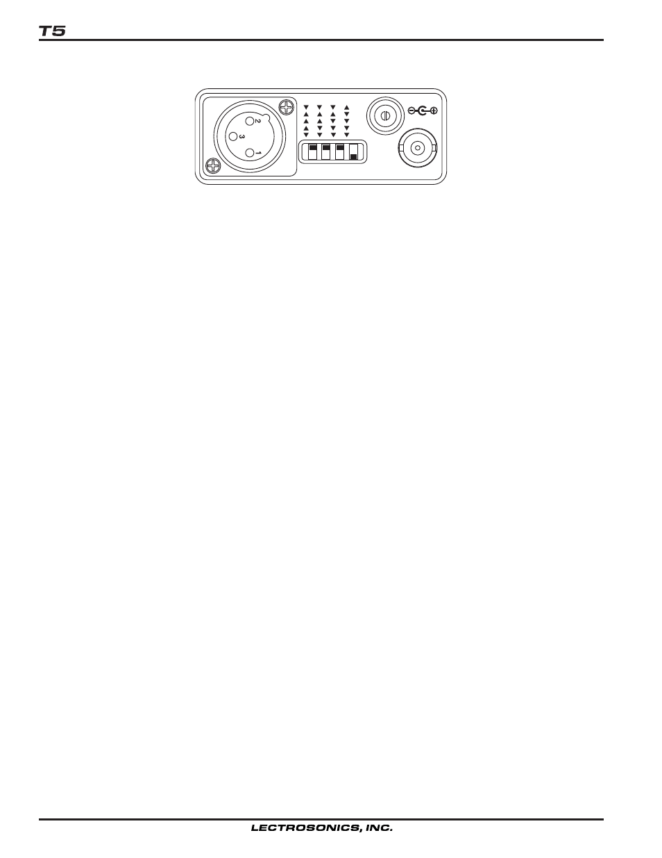
REAR PANEL CONTROLS AND FUNCTIONS
M
O
D
E
12V DC
ANTENNA
CC
MIC
LINE
RTS1
RTS2
1
2
3
4
CH 20
IFB Transmitter
T5 Rear Panel
XLR JACK
Standard XLR female jack will accept a variety of input sources depending on the MODE switches. The pin functions
can be changed to suit the source depending on the** positions of the MODE switches. For detailed information on
the MODE switches see the INSTALLATION AND OPERATION section.
MODE Switches
These dip switches adjust the audio input to accommodate a variety of audio sources. The rear panel is marked with
the most common switch combinations.
CC = Clear Com (unbalanced)
MIC = Mic level (balanced)
For detailed information on these switches see the INSTALLATION AND OPERATION section.
12V DC
External power input. The nominal voltage to operate the unit is 12 VDC but any voltage in the range of 11 VDC to
18 VDC will work. Current consuption is 250 mA maximum.
ANTENNA
This is a standard BNC connector which can accept an integral whip or a cable to a remote antenna.
6