General technical description, Ifb transmitter, T5 ifb transmitter block diagram – Lectrosonics IFBT5 User Manual
Page 3
IFB Transmitter
GENERAL TECHNICAL DESCRIPTION
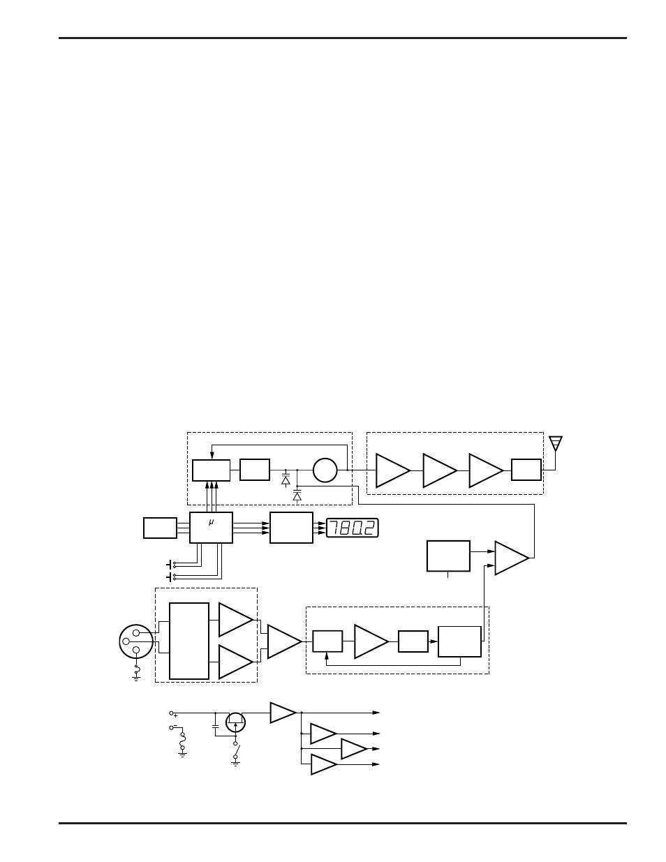
The T5 IFB Transmitter is comprised of a number of functional sub-systems as shown in the block diagram below.
GENERAL
The T5 is designed to operate with the Lectrosonics R5 IFB Receiver and features microprocessor control of 256
frequencies of operation within any one of at least thirteen frequency bands. (See page 10.)
The T5 uses 20kHz deviation for an efficient use of bandwidth. The transmitter circuits are all regulated for frequency
stability and high audio performance. The input amplifier is a discreet differential circuit which can be adjusted to
allow the use of many different input sources.
AUDIO INPUT
The input sensitivity and XLR pin functions can be customized using a clever dip switch circuit. Several different
combinations of gain and input hookup are possible without rewiring the mic connector. Pin 1 of the XLR input
connector is normally connected directly to ground but an internal jumper can be moved if a floating input is desired.
The Audio (+) and (–) are “dry” inputs and can each withstand +/- 50Vdc. Direct connection to a phone line can
damage the inputs.
AUDIO PROCESSOR
The Audio Processor section has several functions. Audio limiting is accomplished in the Shunt Limiter while the
Bandpass filter limits the audio bandwidth to 100Hz at the low end and 10kHz in the upper range. The single band
compandor circuit is one half of a system that requires a matching receiver to decode the signal and restore it to its
original dynamic range.
Filter
Amp
Pre-
Amp
LP
Filter
Transmitter
VCO
PLL &
Prescaler
Frequency Synthesizer
Memory
Controller
Display
Driver
FREQ
Up
Down
Serial
Control
Buffer
Pilot Tone
Oscillator
BP
Filter
1
2
3
Compandor
Shunt
Limiter
Input
Amplifier
XLR
Input
Connector
Power
Control
Mode
Set
Switches
Power Delay
100Hz-10kHz
Output
Amp
Audio Input Interface
Audio Processor
Input
Circuit
Power
On/Off
+10V
Power
11-18 VDC
+5V
Polyfuse
+5.5V
+6V
T5 IFB Transmitter Block Diagram
Rio Rancho, NM – USA
3