Controls and functions, Lcd screen, Power led – Lectrosonics SMQ User Manual
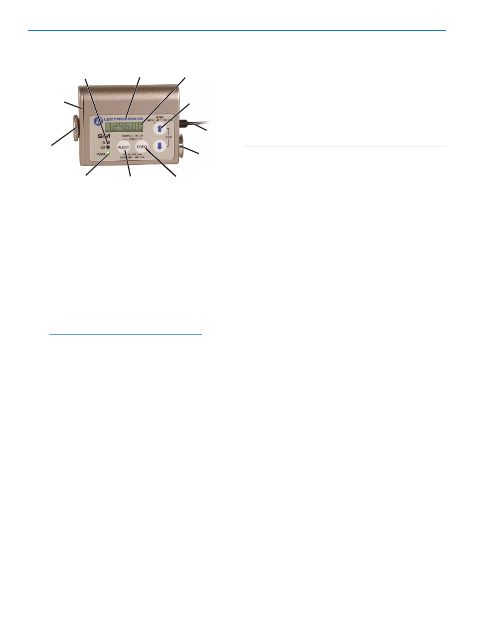
Page 6: Audio input jack, Modulation leds, Audio button, Freq button, Up/down arrows, Antenna, Battery compartment and thumb screw
SM
Controls and Functions
Modulation
LEDs
Control Panel
LCD
Battery
Compartment
Cover Plate
Antenna
Battery
Audio
Compartment
Input Jack
Thumb Screw
UP Arrow
PWR LED
AUDIO Button
FREQ Button
LCD Screen
The LCD is a numeric-type Liquid Crystal Display used
in conjunction with the AUDIO and FREQ buttons, and
the UP and Down arrows, to configure the SM. (See SM
SCREEN SELECTIONS.) It is also used with the
Modulation and PWR LEDs to monitor system operation.
Power LED
The PWR LED glows green when the battery is good.
The color changes to red when there is about 30
minutes of operation left with the recommended lithium
battery. (An alkaline battery will have about 20 minutes
of life left.) When the LED begins to blink red, there are
only a few minutes of life.
Note: A NiMH battery will give little or no warning
when it is depleted. If you wish to use NiMH
batteries in the SM, we recommend trying fully
charged batteries in the unit, noting the length of
time that the batteries will run the unit and then
using the battery timer feature available on most
400 Series receivers.
A weak battery will sometimes cause the PWR LED to
glow green immediately after being put in the unit, but
will soon discharge to the point where the LED will go
red or shut off completely. When the SM is in SLEEP
mode, the LED blinks green every few seconds (See
Sleep Mode, page X).
Audio Input Jack
The input on the SM accommodates virtually every
lavaliere, handheld or shotgun microphone available.
Different line level signals can also be accommodated.
(See
LINE LEVEL SIGNALS and 5-PIN INPUT JACK
WIRING.)
Modulation LEDs
The Modulation LEDs provide a visual indication of the
input audio signal level from the microphone. These
two bicolor LEDs can glow either red or green to
indicate modulation levels.
Signal Level
-20 LED
-10 LED
Less than -20 dB
Off
Off
-20 dB to -10 dB
Green
Off
-10 dB to +0 dB
Green
Green
+0 dB to +10 dB
Red
Green
Greater than +10 db
Red
Red
Audio Button
The AUDIO button is used to display the audio level
setting (0 dB to 44 dB) on the LCD and used in con
junction with the Up and Down arrows to adjust the
audio level input from the microphone.
The AUDIO button is also used with the FREQ button to
enter standby mode and to power the transmitter on or off.
Freq Button
The SM provides 256 individual frequencies, in 100 kHz
increments, across a 25.5 MHz frequency block. The
FREQ Button displays the selected operating frequency
and also toggles the LCD between displaying the actual
operating frequency in MHz and a two-digit hexadeci
mal number that corresponds to the equivalent Lec
trosonics Frequency Switch Setting.
The FREQ button is also used with the AUDIO button to
enter standby mode and to power the transmitter on or off.
Up/Down Arrows
The Up and Down arrow buttons are used to select the
operating frequency, adjust the audio level, or set the
Compatibility Mode.
Pressing both arrows simultaneously enters the lock
countdown. Holding the two arrow buttons until the
countdown completes locks the control panel buttons so
they can only be used to display current settings. “Loc”
is displayed to indicate the controls are locked.
Once locked, the buttons can be unlocked only by
removing the battery, or via the remote control (if
enabled).
Antenna
The fixed flexible cable antenna is supplied with the
transmitter. This antenna is cut to the 1/4 wavelength of
the center of the frequency block (the frequency range)
of the transmitter.
Battery Compartment and Thumb Screw
The large knurled thumbscrew is used to release or
secure the Battery Compartment Cover Plate, allowing
access to the battery.
LECTROSONICS, INC.
6