Preamp level control, Bass filter, Pin input jack wiring (um700) – Lectrosonics UT700 User Manual
Page 24
UDR700 / UM700 / UT700
FB
40k
4k
5
100
4
3
2
1
+
5V Mic Bias
To Mic Amp
POS BIAS (OR GND)
MIC
SOURCE LOAD
LINE IN
NEG GND (OR BIAS)
+
1k
10uF
330pF
330pF
330pF
330pF
Input
Jack
Input Circuit
PIN 3 - Low impedance micro
phone level input for dynamic
microphones. Also accepts
hand-held electret microphones
that have their own battery or
power supply.
PIN 4 - 4 k Ohm source load for
non-Lectrosonics electret
microphones. Use in conjunc
tion with other pins to provide
attenuation of high level input
signals.
20
0dB
-20
-40
-60
10Hz
100Hz
1KHz
10KHz
-3dB @ 71Hz
-20dB @ 50Hz
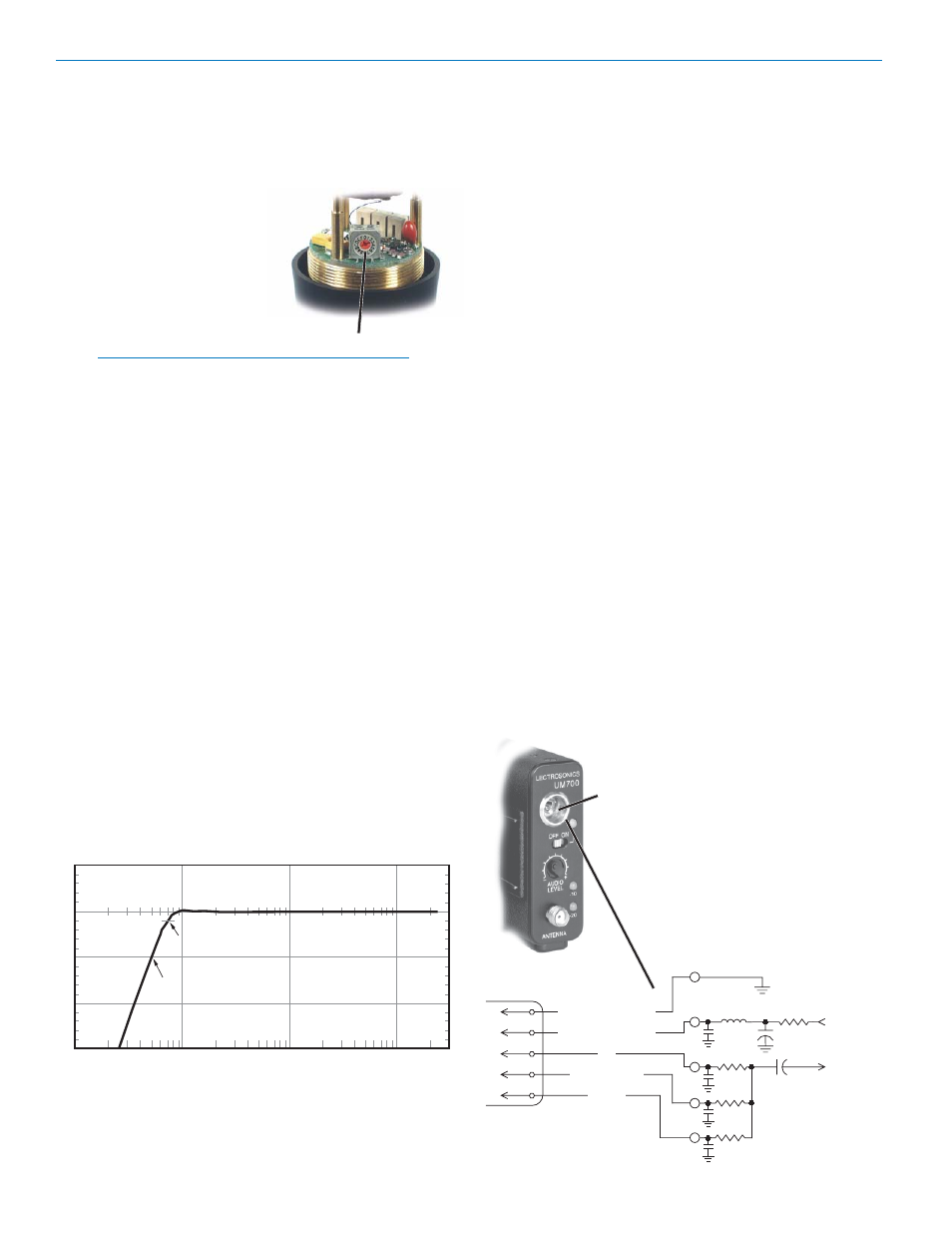
Preamp Level Control
The VariMic™ head includes an attenuator to provide
an additional 15 dB of headroom when needed. The
attenuator should only be used when the normal Audio
Level Control is already turned down as far as it will go
and the signal through the mic
is still too hot. The attenuator
control is a 16-position switch
marked 0 through F. “F” is
minimum attenuation or the
highest signal level. “0” is
maximum attenuation or the
lowest signal level. For the
maximum amount of head
room, set the switch to “0.”
Preamp Level Control
Note: The attenuator should not be used as a level
control. The Audio Level control inside the battery
compartment is the main level control. Adjust the
attenuator only when the Audio Level control is
turned completely down and more headroom is
still needed. Be sure to set the attenuator back to
its original setting (minimum attenuation or “F”) for
normal operation.
Bass Filter
In addition to the tone controls, the UT700 also has a
built in bass filter. This filter is fixed and cannot be
adjusted or defeated. Low frequency noise is more of a
problem with wireless microphones than with conven
tional microphones. With a regular mic, low frequency
wind noise, breath thumps or handling rumble can be
filtered out at the control board before the noise causes
problems with the following electronic circuits or
speaker systems. But with a wireless microphone, the
electronics that will be overdriven are right in the
wireless microphone. Filtering at the control board is
much too late. To solve this problem, the VariMic has a
low frequency filter that is so sharp that it can remove
low frequency noise without affecting any wanted
vocals. It consists of a 36 dB per octave filter circuit to
sharply remove low frequency noise below 75 Hz
without affecting vocal fundamentals.
VariMic Low Frequency Roll-off Filter
5-Pin Input Jack Wiring (UM700)
The wiring diagrams shown in Wiring Hookups For
Different Sources represent the basic wiring configura
tions necessary for the most common types of micro
phones and other audio inputs. Some microphones
may require extra jumpers or a slight variation in the
diagrams shown.
It’s virtually impossible to keep completely up to date on
changes that other manufacturers make to their prod
ucts. It is possible that you may encounter a micro
phone that differs from those illustrated. If this occurs
please visit our web site (http://www.lectrosonics.com)
or call our toll-free number listed in the back of this
manual for assistance. Our Service Department can
answer your questions regarding microphone compat
ibility.
When used on a wireless transmitter, the microphone
element is in the proximity of the RF coming from the
transmitter. The nature of electret microphones makes
them sensitive to RF, which can cause problems with
the microphone/transmitter compatibility. If the electret
microphone is not designed properly for use with
wireless transmitters, it may be necessary to install a
chip capacitor in the mic capsule or connector to block
the RF from entering the electret capsule. (See RF
Bypassing.)
PIN 1- Shield (ground) for positive biased electret
lavaliere microphones. For the increasingly rare
negative biased electret lavaliere microphones, it is
the bias voltage source. It is also the shield
(ground) for dynamic microphones and line level
inputs.
PIN 2 - Shield (ground) for negative biased electret
lavaliere microphones. Bias voltage source for
positive biased electret lavaliere microphones.
LECTROSONICS, INC.
24