General technical description, Figure 1 - ur190 receiver block diagram – Lectrosonics UR190 User Manual
Page 3
GENERAL TECHNICAL DESCRIPTION
A FC
2nd Mixer
Demodulator
RF
LED
Squelch
0dB
LED
-20
LED
O n
Off
Power
L E D
+9V
Helical Resonator
Filter
GA sF ET
Preamp
Helical Resonator
Filter
Double
Balanced
Mixer
1st
Local
Oscillator
CH12
Jack
+9V
Reg
1st IF Amp
and Crystal Filters
2nd
Local
Oscillator
Balanced
XLR
Output
Output Amp
& Level Control
2nd IF Amp
w/LC Filters
Dual-Band
Compandor
16 kHz
Lo-Pass Filter
Audio
Level
Hdph Amp
and Level Control
Headphone
Output
Polarity
Protection
Ant
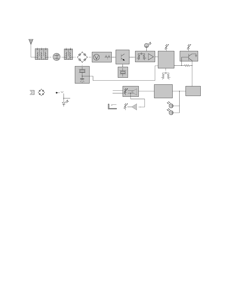
Figure 1 - UR190 Receiver Block Diagram
The UR190 receiver is comprised of six major functional subsystems: the RF front-end amplifier, the
double balanced mixer/local oscillator, the first IF filter, the second IF filter and audio demodulator, the
compandor, and the balanced microphone level output circuit.
The RF front-end amplifier consists of a 5-section helical resonator for high selectivity. Between the
first and second helical resonators, is a low noise GAsFET amplifier. These amplifiers are designed to
provide only enough gain to make up for the inherent loss through the helical resonators. This
combination of low front-end gain, coupled with the extremely high selectivity of the cascaded helical
resonators results in no overloading, even on extremely strong signals. Rejection of out of band signals
is maximized, and intermodulation products are suppressed.
The mixer stage consists of a high level double balanced diode mixer. The oscillator is biased from a
regulated supply, and includes Automatic Frequency Control (AFC) yielding stable performance over
the normal variations in supply voltage. The local oscillator crystal operates at approximately 16 MHz,
and can be adjusted above and below the nominal frequency in order to place the 21.4 MHz IF in the
center of the crystal filter’s narrow passband. The high selectivity of the IF crystal filter stage further
minimizes the possibility of interference from signals on adjacent frequencies.
The second IF filter and the audio demodulator, as well as the squelch and RF output LED drive are
provided by one monolithic integrated circuit. The second IF filter is centered on 1mHz, and drives a
double tuned quadrature type FM demodulator. The squelch circuit is a supersonic noise detector type
and is factory set for a -20dB SINAD level (about .5uV). The squelch level is regulated and
temperature compensated to maintain a consistent squelch level under all conditions.
2