Main window (lcd) – Lectrosonics UCR211 User Manual
Page 8
UCR211
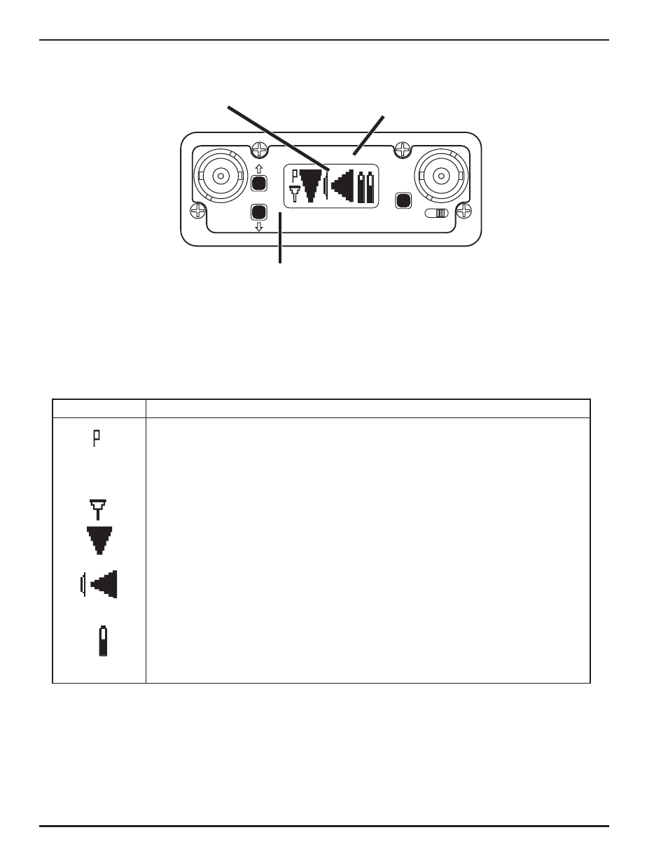
MAIN WINDOW (LCD)
RF levels
reference for RF
level screen icon
Audio Levels - reference levels for
audio signal modulation from
transmitter
Pilot
Div RF
Aud Rx Tx
BAT
-40 -20 0 dB
1000
100
10
1
uV
OFF ON
MENU
SEL
1
2
LECTRO
UCR 21 1
Msin Window (LCD)
The Main Window displays information concerning the
portal to menu selections for setting up the receiver and
condition of the Pilot Tone, antenna phase, RF and audio
searching for clear frequency channels. (See Menu
signal levels and battery conditions for both the receiver
Selections from Main Window and Frequency Scan
and the associated transmitter. It is also the access
Mode.)
Icon
Description
Pilot tone indicator - A steady “P” icon is displayed when a pilot tone from the associ
ated transmitter is present. The icon flashs if no pilot tone is detected and will change to
a small “b” if the pilot tone has been bypassed. To bypass the pilot tone, press and hold
MENU, then press the SELECT Up button. PRess and hold MENU and press SELECT
UP again to restore normal pilot tone squelch.
Antenna Phase indicator - Shows antenna phase switching activity. As the antenna
phase is switched, the symbol will flip vertically.
RF level - Changes in size vertically to indicate the strength of the incoming RF signal.
RF levels are engraved from 1 uV to 1000 uV on the bezel to the left of the LCD.
Audio Levels - Changes in size horizontally to indicate the audio level (modulation) of
the signal received from the transmitter. The icon changes to a solid rectangular block
when the audio signal is being limited in the transmitter. Levels in dB are engraved into
the bezel above the LCD.
Battery Levels - Rx indicates the receiver battery condition and will flash when approxi
mately one hour of operational time is remaining. The Tx symbol works in the same
manner to indicate the transmitter battery condition. The Tx icon usually appears 5 to
10 seconds after the transmitter signal is acquired. When external power is being used,
the Rx battery icon changes to look like a power plug.
LECTROSONICS, INC
8