Installation and operating instructions, Finding clear frequencies – Lectrosonics UCR211 User Manual
Page 12
UCR211
INSTALLATION AND OPERATING INSTRUCTIONS
1. Install a fresh battery or connect an external
power source to the UCR211.
2. Unless frequency settings have been previously
assigned, scan for an open frequency and set
both the receiver and transmitter to that fre
quency. (See Finding Clear Frequencies.)
3. Connect the audio cable to the Receiver Audio
Out XLR jack.
4. Set the Power ON/OFF switch to ON and verify
that the LCD panel activates.
5. Adjust the transmitter gain.
THIS IS PERHAPS
THE MOST IMPORTANT STEP IN THE SET UP
PROCEDURE.
Refer to your transmitter
manual’s Operating Instructions section for
details on how to adjust the transmitter gain. In
general, adjust the transmitter gain so that the
voice peaks will cause the audio modulation
indicators on the receiver and transmitter to show
full modulation on the loudest peak audio levels.
Normal levels should cause the UCR211’s audio
level icon to fluctuate fully. This will result in the
best possible signal to noise ratio for the system.
Note
A common mistake at this point is to use the
transmitter audio gain control to set the overall
audio level of the entire audio system. The
transmitter gain control is not a volume control and
must be set independently of the overall system audio
level. The transmitter gain control is only used to set
the proper modulation of the transmitter. To explain
it another way, it is used to match the transmitter to
the type of microphone and the sound levels that will
be present at that microphone. We encourage users
to either disconnect the rest of the sound system or
turn the sound system gain to minimum to prevent
feedback or overload as the transmitter gain is set.
That way, feedback from the sound system or
overload of other equipment does not get in the way
of setting the transmitter gain properly. Only after
the transmitter gain control is set should the gain of
the rest of the audio system be adjusted to achieve
the desired sound or signal levels.
6. Adjust the Audio Output according to the type of
input on your equipment. Use the LEVEL menu
and adjust the level with the SELECT Up and
Down buttons.
The input levels of different cameras, VCRs, and
PA equipment vary, which may require that you
adjust the AUDIO OUT to an intermediate posi
tion. Try different settings and listen to the
results. If the output of the receiver is too high,
you may hear distortion or a loss of the natural
dynamics of the audio signal. If the output is too
low, you may hear steady noise (hiss) along with
the audio. The UCR211 audio output is designed
to drive any audio input device from microphone
level to +10dBu line level.
Note
The test tone output is especially useful for an exact level
match. With the test tone running, adjust for the maximum
desired peak level using the metering on the connected
device.
Output
Level
25V
XLR
Adjust
Squelch
Non-Polar
OUT
50
2 (HI)
2K
1 (COMMON)
AUDIO
AMP
Caps
2K
3 (LO)
50
UCR211 Simplified Audio Output Circuit
FINDING CLEAR FREQUENCIES
The folllowing procedure will help you identify RF signals
in the area and find clear channels for operating the
wireless system.
1. Ensure transmitter is turned off. Turn on the
receiver and wait a few seconds until the Main
Window appears on the LCD
2. Ensure the receiver is not in PILOT TONE
BYPASS mode. (A “P” will be blinking in the
upper left corner of the Main Window.)
Pilot
-40 -20 0 dB
Pilot Tone Indicator
1000
100
10
BAT
1
uV
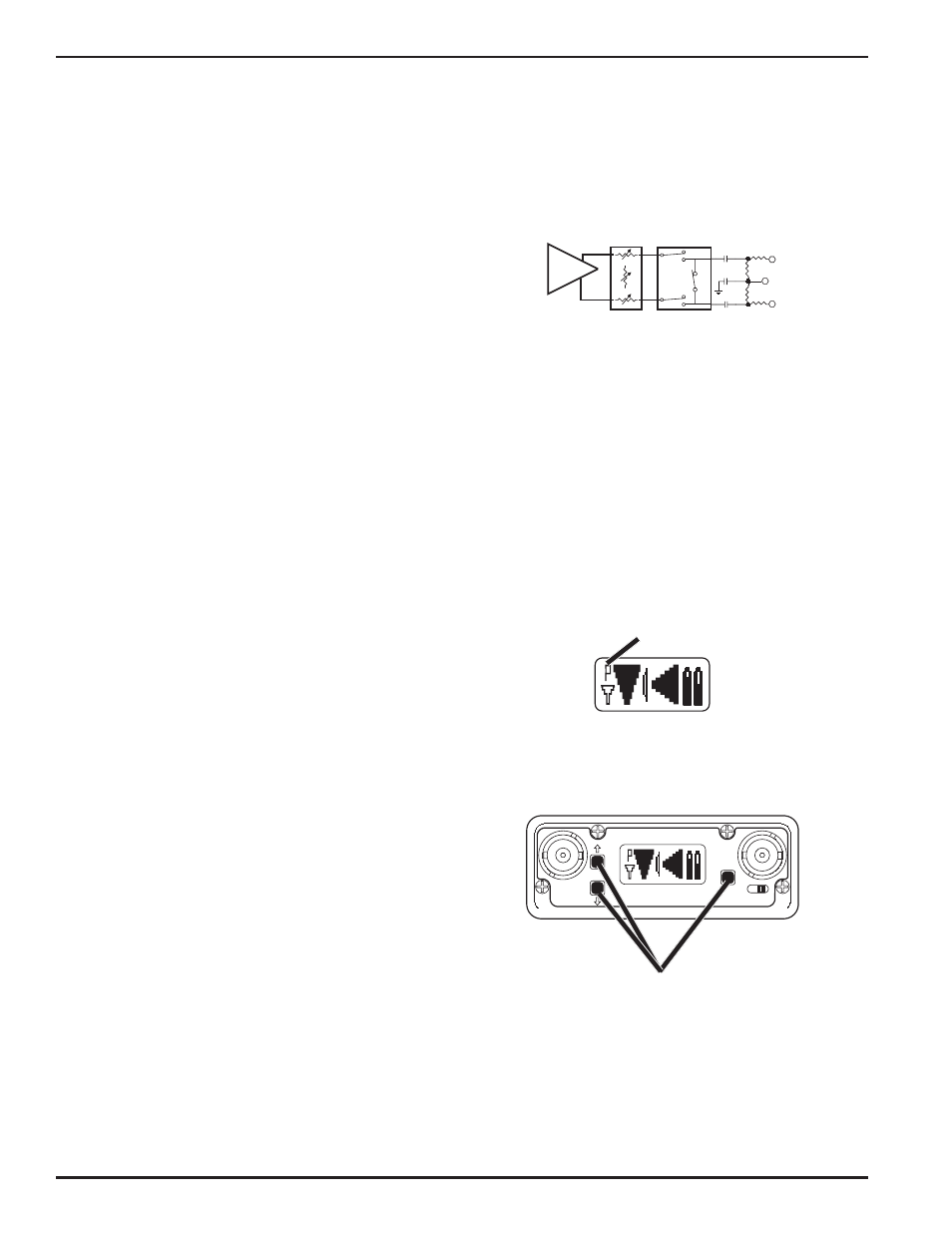
3. Simultaneously press the MENU and SELECT
Up and Down buttons to enter Scan Mode.
Pilot
Div RF
Aud Rx Tx
BAT
-40 -20 0 dB
1000
100
10
1
uV
OFF
ON
MENU
SEL
1
2
LECTRO
UCR 211
Press all three buttons at the same time
and the receiver will start scanning.
4. View the LCD while the receiver is scanning. The
vertical marker will move across the display from
left to right. RF activity will be indicated by dark
areas in the display.
LECTROSONICS, INC
12