Front panel controls and functions, Audio outputs, Lcd screen – Lectrosonics SRb_SRb5P User Manual
Page 8: Menu/sel button, Pwr/back button, Up/down arrow buttons, Rear panel and adapters
SRb5P and SRb Dual Receivers
LECTROSONICS, INC.
8
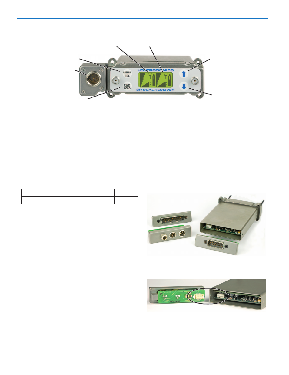
Front Panel Controls and Functions
Audio Outputs
A second set of audio outputs is provided next to the
front panel for use with cameras that have only one au-
dio channel enabled in the slot. One channel can feed
the connector in the camera slot, and the second chan-
nel can be connected to the external audio jack on the
camera with a cable. When the receiver is used outside
of a camera, the front panel jack can be used to feed
audio to a recorder, IFB transmitter or camera while the
rear panel outputs feed the main production mixer.
The front panel 5-pin connector (TA5M type) provides
two balanced outputs with the following pinouts:
Pin 1
Pin 2
Pin 3
Pin 4
Pin 5
Shields
CH1 +
CH1 –
CH2 +
CH2 –
LCD Screen
A backlit, graphics-type Liquid Crystal Display is used
to set up and monitor the receiver. The Main Window
shown here is used during normal operation, to display
RF and audio levels, transmitter battery status, pilot
tone status and diversity activity for both receivers.
MENU/SEL Button
This button is used to select menu items and enter
setup screens during setup.
PWR/BACK Button
Press the PWR/BACK switch to turn the power on.
Press and hold it until the display goes blank to turn
power off. It also functions as a “back” button while navi-
gating the various menus and setup screens to return to
the previous screen or menu item.
The firmware “remembers” whether the receiver was
turned on or off after power is disconnected, and it
returns to that state when power is restored. This allows
the receiver to power up and down as the camera or
external supply is turned on and off.
Press the PWR/BACK button from the Main Window to
briefly display the external power voltage.
UP/DOWN Arrow Buttons
The UP and DOWN arrow buttons are used to select
various options and adjust values in the setup screens,
and provide secondary functions such as locking out
the panel to guard against accidental changes.
Rear Panel and Adapters
Several different panel adapters are available to config-
ure the receiver for use with popular camera slots and
for stand-alone use. The adapters are retained by two
screws through the side panel of the housing, making
them easy to install.
Power and audio connections are made through mating
connectors on the adapter and receiver main circuit
boards.
DOWN Button
MENU/SELECT
Button
POWER/BACK
Button
UP Button
Receiver 1
Receiver 2
LCD Main Window with two channels shown
Audio
Output