Controls and functions, Lcd screen, Battery compartments and thumb screws – Lectrosonics WM - Quick Start Guide User Manual
Page 2: Modulation leds, Power led
LECTROSONICS, INC.
2
Battery Compartment
Caps
Audio
Input Jack
AUDIO Button
LCD
FREQ Button
Modulation
LEDs
PWR LED
UP Arrow
DOWN
Arrow
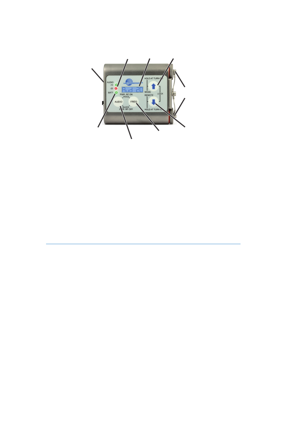
Controls and Functions
LCD Screen
The display is a highly visible backlit LCD with screens for making all setup and level
adjustments. The transmitter can be powered up with or without the RF output turned
on. With the RF output turned off, all adjustments can be made without creating interfer-
ence for other wireless systems in the vicinity.
For normal powering up and down, a countdown appears in the LCD. The buttons must
be held in for the duration of the countdown, which helps to prevent accidentally turning
the transmitter on or off.
The PWR LED glows green when the battery is good. The color changes to red when
there is about 30 minutes of operation left with the recommended lithium battery. An
alkaline battery will have about 20 minutes of life left. When the LED begins to blink red,
there are only a few minutes of life.
Note: A NiMH rechargeable battery will give little or no warning when it is depleted. If you wish to use
NiMH batteries, we recommend trying fully charged batteries in the unit and using the battery timer feature
available in most receivers to determine the available operating time.
A weak battery will sometimes cause the PWR LED to glow green
imme
diately after
the unit is turned on, but will soon discharge to the point where the LED will turn red or
the unit will turn off completely. When the transmitter is in SLEEP mode, the LED blinks
green every few seconds.
Audio Input Jack this is a threaded locking connector
that accepts the Lectrosonics watertight WP connector.
Battery Compartments and Thumb Screws
The large knurled thumbscrews retain the batteries and maintain solid battery contact.
The lanyard keeps the battery caps attached, but it can be removed if desired using a
1/16 inch hex key (Allen wrench).
Modulation LEDs
Proper input gain adjustment is critical to ensure the best audio quality. Two red/green
LEDs will glow to accurately indicate modulation levels. The input circuitry includes a
wide range DSP-controlled limiter to prevent distortion during high peak levels.
It is important to set the gain (audio level) high enough to achieve full modulation during
louder peaks in the audio. The DSP-controlled limiter can handle peaks over 30 dB
above full modulation. Full modulation is indicated when the -20 LED first turns red.
With an optimum setting, the -20 LED will flicker red during operation. If the LEDs never
flash red, the gain is too low.
Power LED