Pin input jack wiring – Lectrosonics UM400a User Manual
Page 10
UM400a
LECTROSONICS, INC.
10
The wiring diagrams included in this section represent
the basic wiring necessary for the most common types
of microphones and other audio inputs. Some micro-
phones may require extra jumpers or a slight variation
on the diagrams shown.
It is virtually impossible to keep completely up to date on
changes that other manufacturers make to their products,
thus you may encounter a microphone that differs from
these instructions. If this occurs please call our toll-free
number listed under Service and Repair in this manual or
visit our web site at:
www.lectrosonics.com
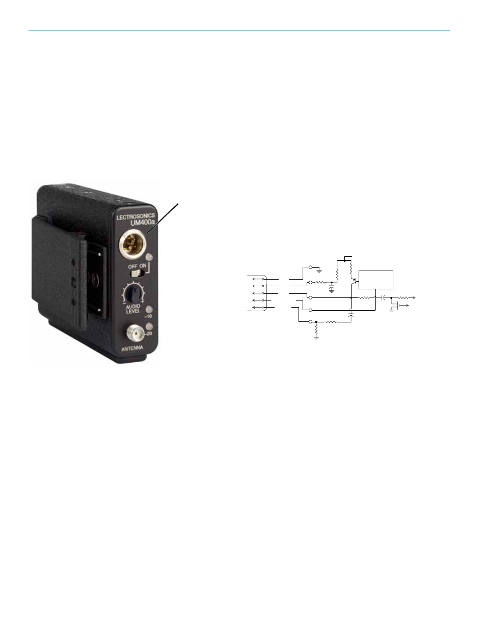
5-Pin Input Jack Wiring
Audio Input Jack
The Audio Input Jack for the UM400a is wired as shown
below:
PIN 1 Shield (ground) for positive biased electret lava-
liere microphones. Shield (ground) for dynamic
microphones and line level inputs.
PIN 2 Bias voltage source for positive biased electret
lavaliere microphones.
PIN 3 Low impedance microphone level input for
dynamic microphones. Also accepts hand-held
electret microphones provided the microphone
has its own built-in battery.
PIN 4 Bias voltage selector for Pin 3. Pin 3 voltage (0, 2
or 4 volts) depends on Pin 4 connection.
Pin 4 tied to Pin 1: 0 V
Pin 4 Open:
2 V
Pin 4 to Pin 2:
4 V
PIN 5 High impedance, line level input for tape decks,
mixer outputs, musical instruments, etc.
SM Equivalent Input Circuit Wiring
10k
1k
5
4
3
2
1
To Virtual Ground
Audio Amplifier
BIAS
MIC
BIAS SELECT
LINE IN
GND
+
30uF
+5 VDC
Servo Bias
Pin 4 to Pin 1 = 0 V
Pin 4 Open = 2 V
Pin 4 to Pin 2 = 4 V
+
To Limiter Control
30uF
500 Oh
m
100 Ohm
2.7K
200 Ohm
+
3.3uF
100 Ohm