Anritsu 0701012 User Manual
Page 47
Sensor Operational Tests
Linearity Test
MA24106A UG
5-7
7. Set up the test for the second 20 dB range as follows:
a. Remove the 10 dB attenuator from in between the reference sensor and splitter and connect the
reference sensor directly to the splitter.
b. Remove the MA24106A from the splitter and connect the 10 dB attenuator between the splitter
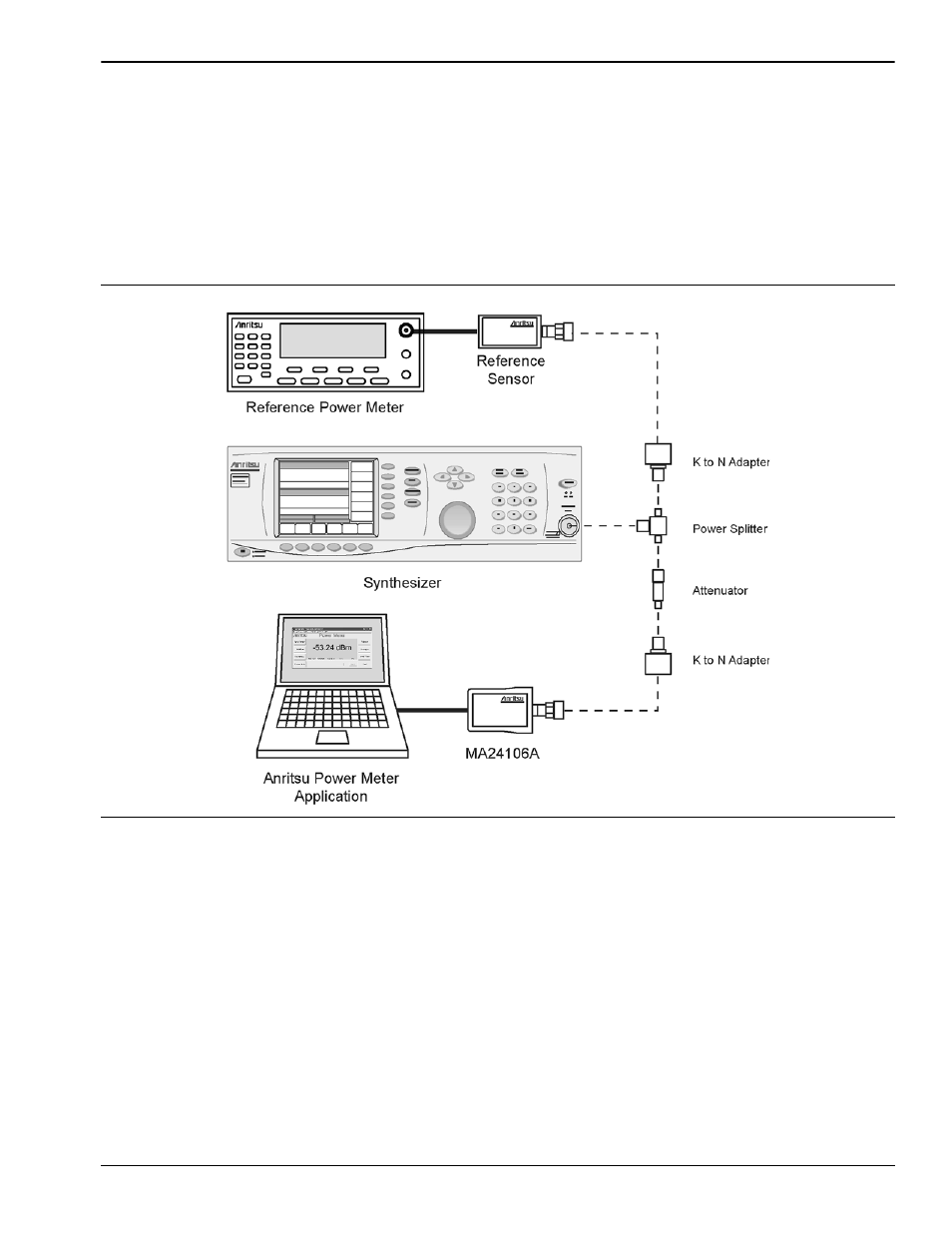
and the MA24106A power sensor (see Figure 5-3).
c. Turn Off the synthesizer’s RF output and perform a low-level Zero of both the Reference sensor
and the MA24106A.
d. Turn On the synthesizer’s RF output.
e. Set the synthesizer output level to +10 dBm and then adjust it until the sensor/meter under test
reads as close as possible to the value obtained above in step 6e.
8. Record data for the next 20 dB range
a. Read and record the power indicated by the reference meter in the appropriate place in Table 5-4.
b. Lower the output power level of the synthesizer to +5 dBm.
c. Record the reference meter and the MA24106A power sensor readings in the appropriate place in
Table 5-4.
Figure 5-3.
Linearity Test Setup