Anritsu 0701012 User Manual
Page 46
Linearity Test
Sensor Operational Tests
5-6
MA24106A UG
n. Increase averaging on the MA24106A by clicking the Averages button, enter “16” and then click
Apply
.
2. Apply the appropriate Cal factor to the reference sensor per the manufacturer’s procedure.
3. Apply the appropriate Cal factor to the MA24106A as follows:
Click the Frequency button on the Power Meter application, and then enter the frequency of the
measurement in GHz.
4. Turn Off the synthesizer’s RF output and perform a low-level Zero of both the Reference sensor and the
MA24106A.
5. Turn On the synthesizer’s RF output.
6. Record data for the first 20 dB range as follows:
a. Record the power reading by the reference meter in the appropriate space in Table 5-4.
b. Record the power reading by the MA24106A in the appropriate space in Table 5-4.
c. Set the synthesizer power to +15 dBm.
d. Record the reference meter and the MA24106A power sensor readings in the appropriate places in
Table 5-4.
e. Repeat the measurement for synthesizer output levels of +10, +5, and 0 dBm.
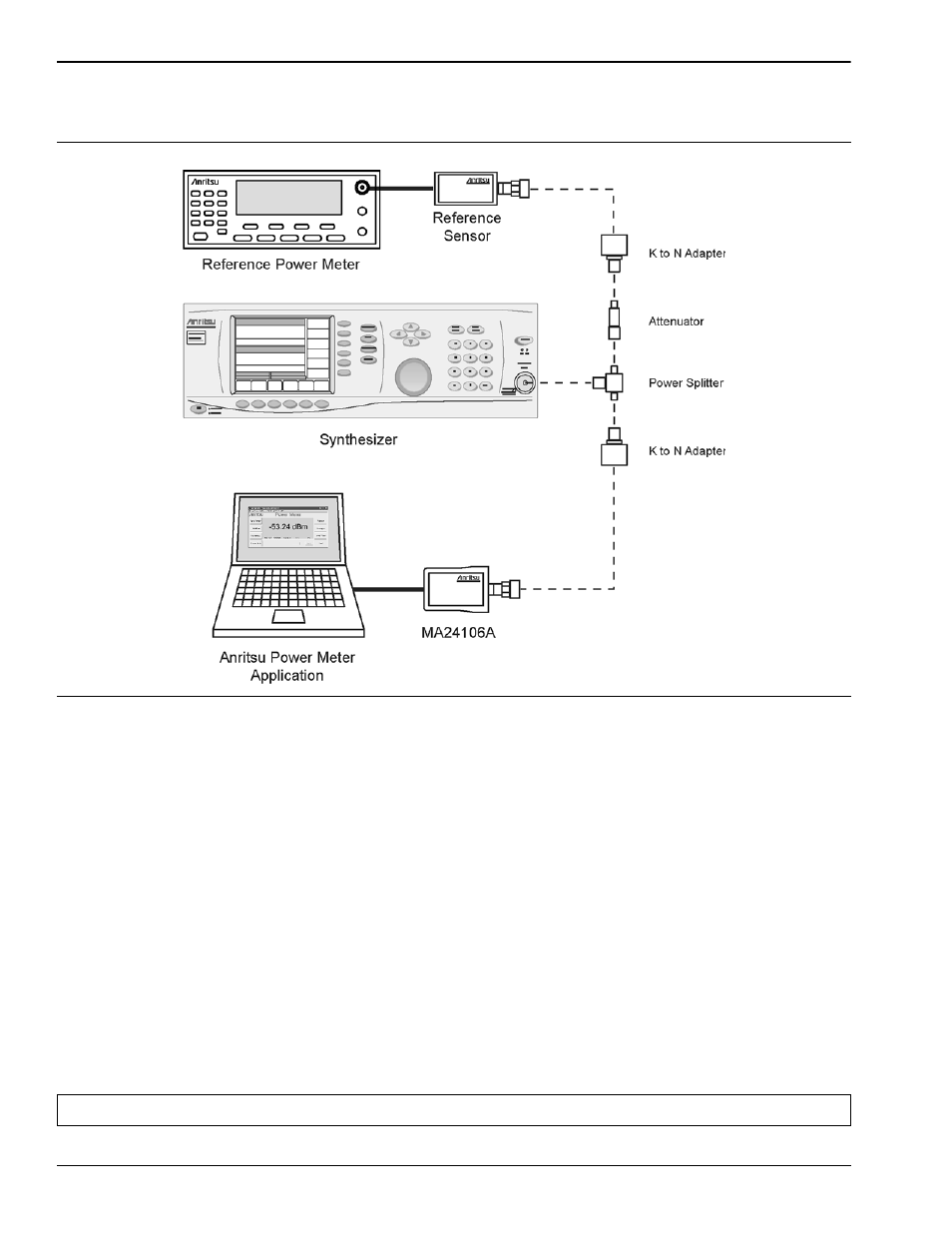
Figure 5-2.
Linearity Test Setup
Note: The MA24106A power measured at 0 dBm will be used in step 7e, below.