5 wiring schematic 5.6 accessories, Keypad microphone, Led keypad light led push button speaker – DoorKing 1812 Plus User Manual
Page 42
1812-161-L-12-11
40
SPEAKER
VOL
MIC VOL
MASTER
CODE
1970-010
18
11
1 2 3 4 5 6 7 8 910
17
16
15
14
13
12
11
10
9
8
7
6
5
4
3
2
1
J2
J1
J3
Secondary Keypads: Allows remote activation of the system relays by use of the access codes. Does not provide any voice
communication to the main unit or to the resident telephone. P/N 1812-082 (surface mount); P/N 1812-197 (flush mount)
Surge Suppressors:
High voltage (115 V) suppressor. P/N 1876-010.
Phone line suppressor. P/N 1877-010.
Low voltage (28 V) suppressor. P/N 1878-010.
Mounting Posts:
Gooseneck mounting post with concrete base plate. P/N 1200-045.
Gooseneck mounting post – direct burial. P/N 1200-046.
Telephone Test Set: Includes clips, cord and carrying case. P/N 1800-050.
Back-Up Battery: 12 volt .8 amp hour gel cell provides stand by power during power interruptions. P/N 1801-008.
Postal Lock Box: Provides a means for the mail carrier to enter the premise to deliver mail. P/N 1402-080.
Magnetic Locks: A variety of magnetic locks are available to meet individual application requirements. Contact your DoorKing
dealer.
Electric Strikes: A variety of electric strikes are available to meet individual application requirements. Contact your DoorKing
dealer.
CCTV Camera: Camera mounted in phone system. P/N 1812-130 Color, P/N 1812-040 Black & White. Not available for the wall
mount model.
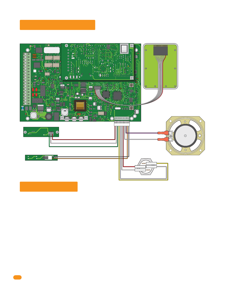
5.5 Wiring Schematic
5.6 Accessories
Keypad
Microphone
1998-010
LED Keypad Light
LED Push Button
Speaker
Purple
Red
Wire
Right
J3 10-Pin Keypad Plug Position
on Circuit Board - Red Wire Left
J2 11-Pin Door
Accessories Plug
White
White
Yellow
White
Red
Gray
Red
Orange
White
Green
1972-011
OV