Onnect, Perator, Ontrol – Controlled Products Systems Group 790919 User Manual
Page 3: Anel, Heck, Otor, Irection, Otation
RA
DI
O
1-455D115 = 115V
1-455D = 230V
F2
F1
M
M
K
+
OP
-
CL
+24 V
FSW
NC
-
B
-
STOP
A
+
TX
FSW
W. L.
LOCK
9
10 11 12 13 14 15 16 17 18 19
22 23 24 25
LAMP
COM OP
CL
MOTOR 1
MOTOR 2
CL
COM
OP
1
2
3
4
5
6
7
8
20 21
FC
A
1
FC
A
2
F
CC2
F
CC1
V1-4
61C455D
F
-
+
J2
J6
J4
J5
J1
J3
N
L
MAIN
Page 3
November, 2003
455 D Control Panel Installation Instructions
C
ONNECT
THE
O
PERATOR
(
S
)
TO
THE
C
ONTROL
P
ANEL
WARNING!
Turn the main power off before you
make any electrical connections or before
programming.
C
AUTION
:
The operators are grounded only by
the grounded circuit the installer provides.
U
SING
A
J
UNCTION
B
OX
If an operator is more than 2 ft away from the control
panel, you must use a junction box for connection. Use
a U. L. Listed cord grip where the operator cord enters
the junction box.
Note: If you have a one-leaf gate design, the
operator must be connected to Motor 1 (terminals
1,2, & 3)
To wire up motor 1, connect the white wire to terminal
1(on the J4 terminal strip), the black wire to 2, and the
red wire to 3. Wire each leg of the capacitor (supplied)
to terminals 2 & 3.
Note: If you want to delay the closing of one gate
leaf in a two-leaf gate design, be sure to connect
its operator to Motor 1.
In order to wire motor 2 in a bi-parting system, connect
the white wire to terminal 4 (on the J4 terminal strip),
the black wire to 5, the red wire to 6. Wire each leg of
the capacitor (supplied) to terminals 5 & 6.
C
HECK
THE
M
OTOR
’
S
D
IRECTION
OF
R
OTATION
After you have connected the main power supply, and
the operator(s) to the control panel, you need to check
the direction of rotation for each operator motor in your
gate design.
Note: To check a motor’s direction of rotation,
you must have three closed circuits on terminal
block J1. Install one circuit between terminals 11
and 16, another circuit between terminals 12 and
19, and another circuit between terminals 13 and
19.
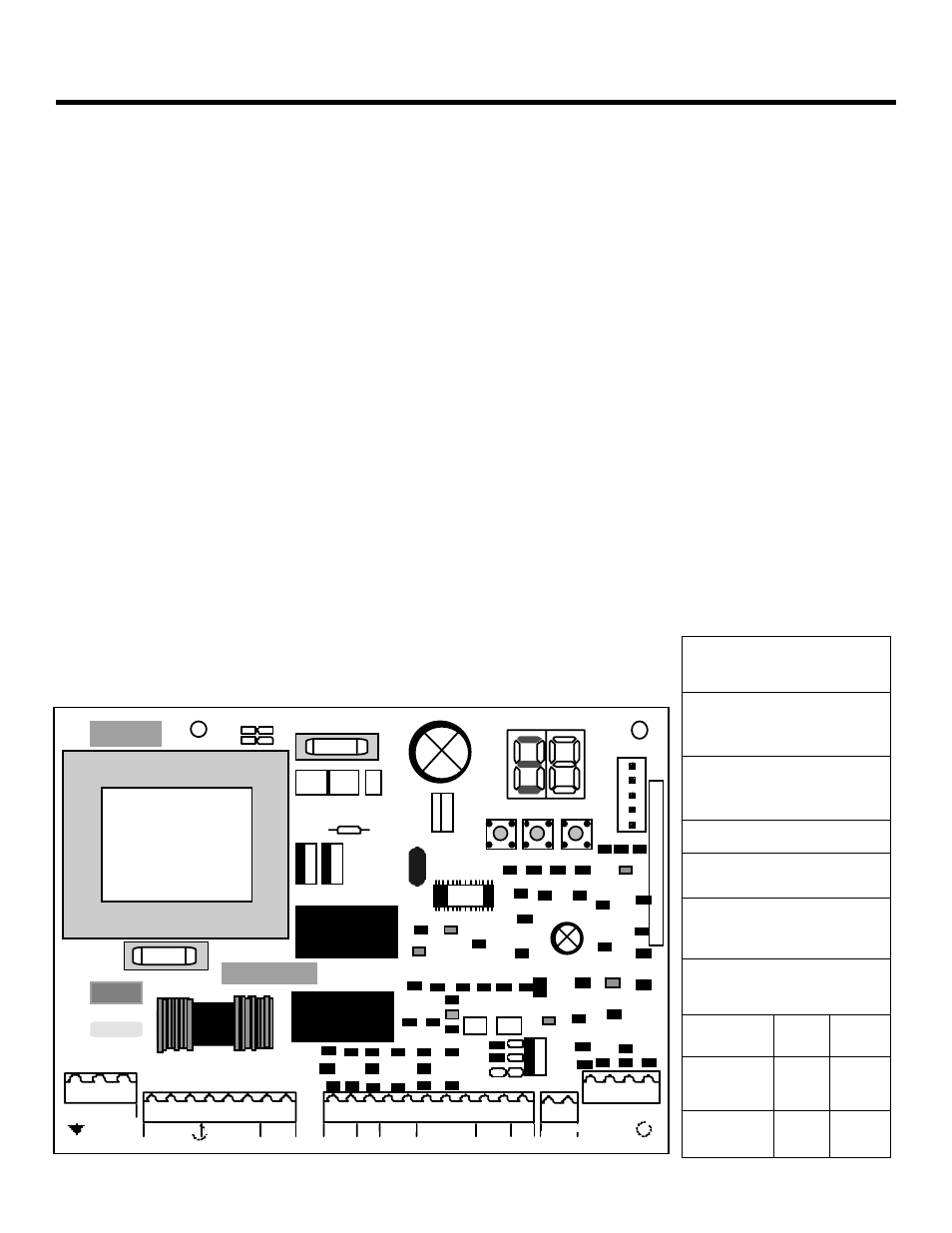
Figure 1. The 455 D Control Panel
J3
terminal block for main
power supply
J4
terminal block for
connecting the operator(s)
J1
terminal block for low-
voltage accessories
J2
quick connector port
F
Function Push Button
—
Programming Push
Button
+
Programming Push
Button
FUSES
220
VAC
115
VAC
F1
Main Power
5 A
10 A
F2
A
ccessories
800
mA
800
mA