Gate arm installation (cont.) – Controlled Products Systems Group SWG-111 User Manual
Page 7
SWG Swing Gate Operator Installation Guide
- 5 -
P1227 Revision X5 2-13-2013
Gate Arm Installation (Cont.)
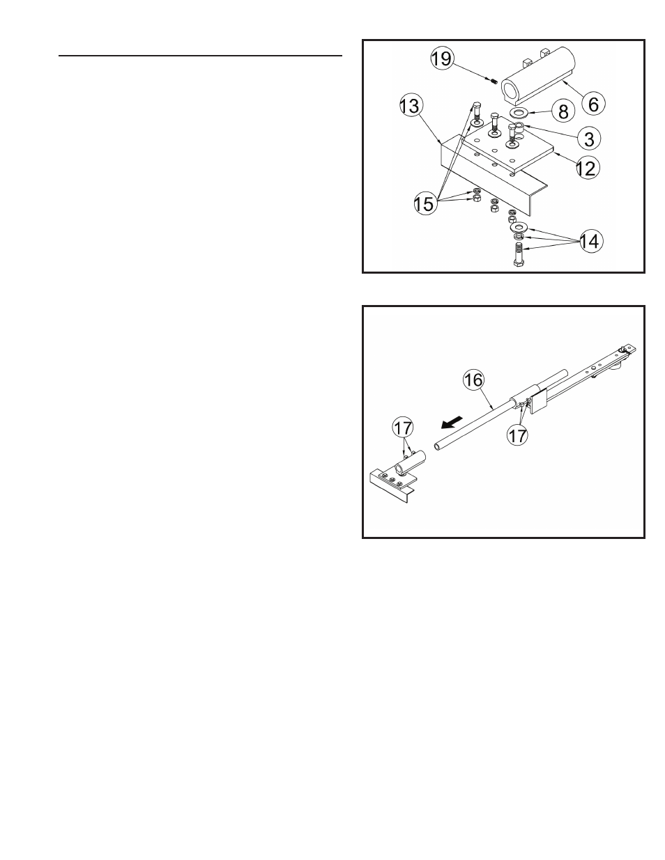
Gate Plate Installation
See Figure 6. Angle iron (not supplied) (13) should be
welded to the gate prior to this step. Attach the gate plate
(12) to the angle iron using 3/8 bolts, fl at washers, lock
washers and hex nuts (15). Slide a 1/2-13 x 1 1/4” bolt, 1/2”
lock washer, 1/2” fl at washer (14), and a black spacer (3)
through the gate plate. Place a nylon washer (8) over the
opening in the gate plate. Thread the bolt into the hole in the
gate clamp (6) and tighten carefully. Do not overtighten!
Tighten set screw (19) to further lock hex bolt (14) in place.
Choosing Good Harmonics
Good harmonics are necessary to minimize wear and tear
on the operator. The gate will have smoother starts and
stops when the arm is installed with good harmonics. The
gate will have smooth starts and stops when the gate arm
folds over itself when the gate is fully open. Avoid setting up
the gate arm where the crank arm is parallel to the gate leaf
when the gate is open.
Pipe Link Installation
See Figure 7. Slide the pipe link (16) through the arm
assembly as shown. Place the 5/16” square bolts in the gate
clamps (17) and tighten carefully. Do not overtighten!
Setting the Arm Lengths
Most installations will use the standard dimensions specifi ed.
If non-standard mounting is required, contact the factory for
information.
Figure 6. Gate Plate Installation
Figure 7. Pipe Link Installation