Model bgus-d exploded view – Controlled Products Systems Group BGUS-18-221 User Manual
Page 25
BGUS
• BGUS-D Barrier Gate Operator Installation Guide
- 23 -
P1275 Revision X2 8-11-2011
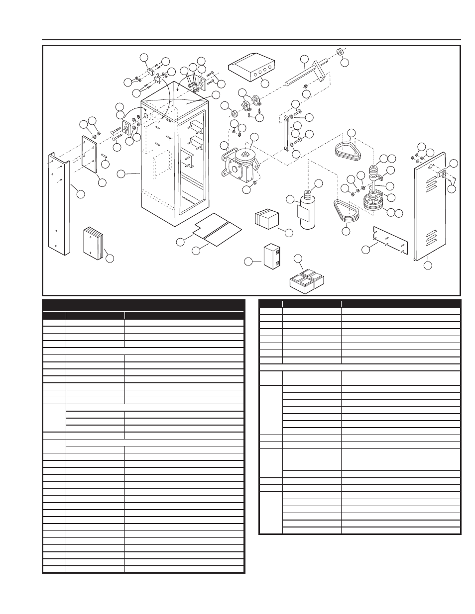
Model BGUS-D Exploded View
9
10
47
30
34
2
1
29
47
30
6
11
42
40
40
42
38
30
47
6
11
29
33
43
44
58
65
19
21
7
33
59
56
55
12
26
56
55
28
59
72
24
74
75
22
54
53
5
52
3
80
17
23
51
60
31
47
30
18
60
25 61
8
71
73
76
MODEL BGUS-D MECHANICAL PARTS LIST
REF. #
PART #
DESCRIPTION
1
2110-839
Enclosure only (without Door)
2
2100-2142
Removable Enclosure Top
3
2110-318*
Louvered Door Assembly with Lock
2100-2141
Latch for Enclosure Top
* Specify color and texture
5
2220-008
Lock Assembly with Keys
6
2110-746
Bearing Block Assembly Kit
7
2110-170
Drive Shaft Assembly
8
2110-732
Gate Arm Flange
9
2100-1886
Arm Attachment Channel
11
2200-136
Flange Bearing only
12
2110-441
Connecting Link with Bearings
17
MOTOR
2500-1902
Motor 24VDC
2510-243
Brush Replacement Kit
2110-834
Motor Mounting Bracket (not shown)
18
2100-364
Intermediate Shaft
19
GEAR REDUCER 75:1
2110-117
Gear Reducer and Crank Arm Assembly
21
2200-917
Reducer Pulley, 7” (2 required)
22
2200-918
Intermediate Pulley, 2” (2 reqiured)
23
2200-151
V-Belt, 25” (2 reqiured)
24
2200-235
Motor Pulley, 1-5/8”
25
2200-011
Intermediate Pulley, 6”
28
2200-208
V-Belt, 26” (2 reqiured)
29
2400-178
Carriage Bolt, 3/8”-16 x 1-1/2”
30
2400-015
Hex Nut, 3/8”-16
31
2400-017
Flat Washer, 3/8”
32
2400-182
Wing Nut, #10-32
33
2200-314
Set Collar, 1-1/4”
34
2400-474
Spring Pin, 3/8” x 2”
35
2400-043
Star Washer, #10
36
2400-032
Hex Nut, #10-32
37
2400-049
Screw, #8-32 x 3/8”, Self-tap
38
2500-029
Limit Switch
40
2400-246
Screw, #6-32 x 2-1/4”, Pan-head
REF. #
PART #
DESCRIPTION
42
2400-069
Keps Nut, #6-32
43
2300-028
Limit Cam
50
2400-238
Key, 3/16” x 3/16” x 1-1/4”
51
2400-254
Key 3/16” x 3/16” x 3”, Intermediate Shaft
55
2400-188
Thrust Washer
56
2400-165
Shoulder Bolt, 1/2”-13 x 2”
60
2200-222
Bearing, Pillow Block
61
2400-133
Key 1/4” x 1/4” x 2-1/4”, Intermediate Shaft
72
2100-1995
Power Disconnect Box and Transformer Mounting
Bracket
73
2510-432
Power Box Assembly
2500-2411
Power Switch
2500-2413
Power Outlet
2500-2473
Relay, 24 VDC
2500-1768
Bridge Rectifi er
2500-1819
Fuse Holder
2500-1748
Fuse, 10 Amp, Slow-Blow
74
2100-1804
Rear Accessory Shelf
75
2100-1820
Front Accessory Shelf
76
2510-182
Battery Assembly
(Linear supplied - some distributors supply other
batteries)
2500-1118
Battery, 12V (2 required)
2520-524
Wiring Harness Assembly (not shown)
77
2100-2143
Power Box Mounting Strap
80
2510-439
APeX Module and DC Motor Board Assembly
2500-2393
APeX Module
2500-2399
APeX DC Motor Module
2100-2104
APeX Mounting Plate
2300-1025
Plastic Cover Only
2510-423
Knob Kit