Controlled Products Systems Group 9150-080 User Manual
High voltage connection, Automatic limits chain adjustment, Circuit board settings
4910
4910
RE
VERS
E
SENS
ITIV
ITY
RE
VE
RS
E
LOOP
EXIT
LOOP
KEY
SWITCH
DO
ORK
ING
460
2-0
10
SW1
SW2
OPE
N
TIME
R
W
ARNI
NG
MO
VIN
G G
ATE
CA
N C
AU
SE
Ope
rate
ga
te on
ly w
he
n ga
te a
rea
is
in
sig
ht
and
fre
e o
f pe
ople
and
ob
str
uction
s.
Do
no
t allo
w c
hildr
en
to
pla
y in
gate
are
a
or
ope
rate
ga
te.
Do
no
t sta
nd
in
gate
pa
th
or w
alk
thr
ou
gh
path
wh
ile
ga
te is
m
oving
.
Rea
d ow
ne
r’s m
anua
l and
sa
fety
ins
truc
tion
s.
SE
RIO
US
IN
JU
RY
OR
DE
ATH
CLA
SS
CE
RT
IFIE
D T
O
CAN
/CS
A C2
2.2
NO
. 2
47
CO
NF
OR
MS
TO
AN
SI/U
L-3
25
VEH
ICU
LA
R G
ATE
OP
ER
AT
OR
HP
53382
MO
DE
L
SER
IAL
VO
LT
S
PH
ASE
AMPS
60 H
z
MA
X
GA
TE L
OAD
Doo
rK
ing
, In
c.,
Ing
lew
ood
, C
A
ON
ON
RE
VE
RS
E
SE
NS
ITI
VI
TY
RE
VE
RS
E
LOO
P
EXI
T
LOO
P
KE
Y S
W
ITC
H
DO
OR
KI
NG
46
02-0
10
SW
1
SW
2
OPE
N
TIME
R
NC
1
2
3
4
5
NO
2.5”
Concrete Pad
Center
14.5”
Conduit Area
Electronic Box
8.5”
Hot Hot
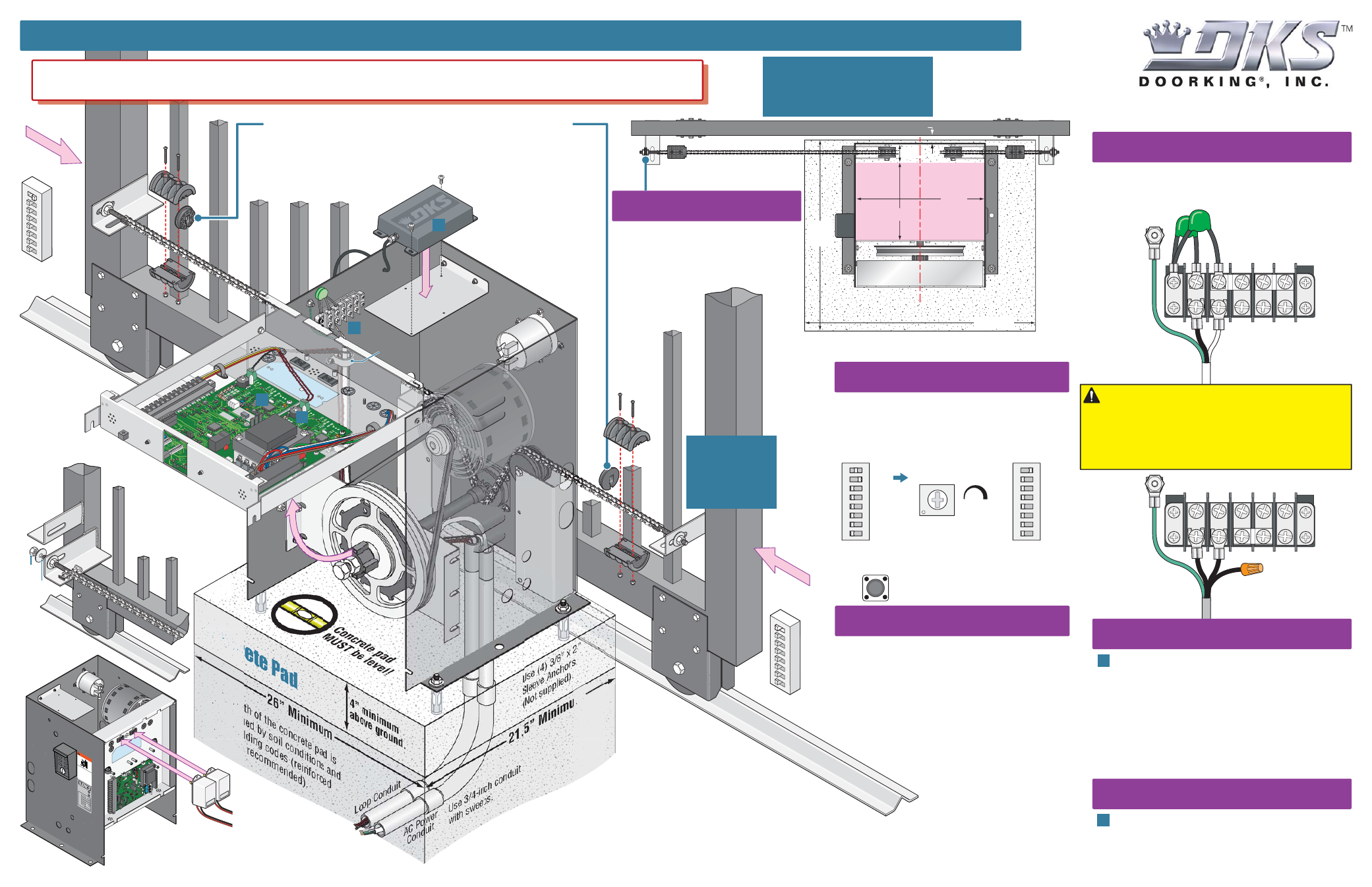
QUICKSTART “BASIC” GUIDELINES FOR MODEL 9150 - FRONT INSTALLATION MOUNTED ON A CONCRETE PAD
120 Glasgow Avenue
Inglewood, California 90301
U.S.A.
Model 9150 is intended for installation only on sliding gates used for vehicles.
Pedestrians must be supplied with a separate access opening. For safety and installation instructions, please refer to the Installation/Owner’s manual.
Copyright 2010 DoorKing, Inc. All rights reserved.
9150-066-E-8-10
Concrete pad
MUST be level!
This depth of the concrete pad is
determined by soil conditions and
local building codes (reinfor
ced
concrete recommended).
Loosen the 2 nuts under the
electronic box to swing box up.
Use 3/4-inch
co
nduit
with sweeps.
Use (4) 3/8” x 2”
Sleeve Anchors
(Not supplied).
Loop Conduit
AC Power
Conduit
4” minimum
above ground.
Opening
Direction
Switch 1
OFF
.
21.5” Minimum
26” Minimum
Idler
Wheel
Use existing
wire restrainers
to keep wire
away from
moving
parts.
Concrete Pad
• Chain MUST be parallel to gate!
• Chain bracket MUST line up with
idler
wheels!
Chain brackets
MUST be mounted
the same height as
the chain on the
idler wheels!
Chain
Bracket
SW 1
1
2345678
ON
Opening
Direction
Switch 1
ON
.
SW 1
1
2345678
ON
B
B
A
C
High Voltage Connection
Tip:
It is recommended that a surge suppressor be
installed on the high voltage power lines.
GATE OPERATOR MUST BE PROPERLY GROUNDED!!
The 9150’s open/close limits DO NOT have to be
physically adjusted. Every time the 9150 is powered
up, the first open command will automatically run
“2 open/close gate cycles” that will locate and
remember the gate’s open and close limit
positions. These limit positions are determined by
where the physical stops have been installed. It does
not matter what position the gate is in before
running this sequence. The gate will function
normally after this automatic sequence
has finished.
Adjust the chain nuts to tighten the chain.
The chain should sag no more than one
(1) inch per 10 feet of chain travel.
Do not over tighten the chain.
Automatic Limits
Chain Adjustment
Note:
Auto-close timer should be
on before running this sequence.
115 VAC
Chassis Ground
White - Neutral
Black - 115 VAC Hot
Green - Chassis Ground
Hot Neu
Every time the 9150 is powered up, the First open
command will automatically run “2 open/close gate
cycles” that will locate and remember the gate’s open
and close limit positions. See “Automatic Open/Close
Limit Adjustment” in Installation/Owner’s manual for
more information.
208/230/460 VAC
Chassis Ground
For 208, 230 and 460 Volt
3-phase input, use only two legs
of the incoming 3-phase power.
1” minimum space between the gate and the operator housing.
21.5”
Min.
26” Min.
Concrete Pad and Conduit Area
Circuit Board Settings
ON
1
2
345678
SW 2
ON
1
2
345678
SW 1
1. Opening Direction (See Illustration)
2.
ON
3. OFF
4. OFF
5. OFF
6. OFF
7. OFF
8. OFF
1.
ON
2. OFF
3. OFF
4. OFF
5. OFF
6. OFF
7. OFF
8. OFF
Auto-Close Timer
Adjust 1 to
23 sec.
1
23
Note:
SW 2, switch 1 is
turned on when plug-in
exit loop detector is
installed.
SW 1, Switch 1 -
Must OPEN the gate upon initial AC
power up and open command. If the open command
begins to close the gate, turn AC power off and
reverse this switch.
“Basic” Setting of DIP-Switches
OPEN
TIMER
Cycles the operator
when pressed.
Key Switch
High Voltage
AC Input Wire
High Voltage
AC Input Wire
B
Radio Receiver
C
Not included - Refer to a specific Radio Receiver
Manual (available from
www.dkaccess.com
) for
more information on radio receivers and antenna
installation.
Plug-In Loop Detectors
Not included - Refer to the Installation/Owner’s
manual AND Loop Information Manual (available from
www.dkaccess.com
) for more information on loops
and plug-in loop detectors.
Important Note:
DoorKing highly recommends that
loops and loop detectors are installed with this slide
gate operator. A loop detection system will preventing
the gate from automatically opening or closing on a
vehicle when it is in the gate’s path.
DO NOT
power up and cycle the operator without “Physical Stops” installed
to stop the gate in the open and close positions, (Chain stops are included with
the operator but other physical stops can be used) damage could occur to the
gate and operator.
Chain stop’s rubber
bumpers face toward
operator. They will make
contact with the operator
housing during the initial
automatic open/close
limits setting
sequence.
Physical Stops MUST be Used to Stop Gate
Anti-
Grounding
Plate
Connect Chain
Bracket
and
Chain
to Gate
Chain
Nut
Chain
Bolt
Option 2
Maste
r
Link
Option 1
Gate
Frame
Chain nut and
chain bolt should not
protrude past gate frame.
Wire
Restrainer
Power safety and opening devices
that require 115 VAC power.
Two 115 VAC Convenience Outlets