Sw 1 dip-switches sw 2 dip-switches, Sw 1, Sw 2 – Controlled Products Systems Group 6050-080 User Manual
Page 2: Switch function setting description, Important
Every time the operator is powered up, the First open command
will automatically set the open and close limits of the gate.
SW 1
1
ON
2
3
4
5
6
7
8
SW 2
1
ON
2
3
4
5
6
7
8
SW 1 DIP-Switches
SW 2 DIP-Switches
SW 1
SW 2
Note: After a DIP-switch setting is changed, power must be turned
OFF and then turned back on for the new setting to take affect.
Switch Function
Setting
Description
OFF
ON
OFF
ON
OFF
ON
OFF
ON
1-OFF
1-OFF
1-ON
1-ON
2-OFF
2-ON
2-OFF
2-ON
Auto-Close
Timer
Slide Gate
Swing Gate
Dual Operators
Single Operator
Circuit
Board
Relay
3
4
5
7
1 and 2
Auto-close timer is OFF. Manual input required to close gate.
Auto-close timer is ON. Adjustable from 1-23 seconds to close gate.
OFF for Slide gate operator (DO NOT use for 6050/6100).
Normal Setting. ON for Swing gate operator (Switch MUST be ON for 6050/6100).
OFF
ON
3-Button
Single Button
6
OFF when using a 3-button station (DoorKing 3-button control stations only).
ON when using a single button control.
Switch must be OFF when bi-parting (dual) gates are used.
Switch must be ON for single operator.
OFF
ON
Tamper Protect
8
Tamper protect is OFF.
Normal Setting. Tamper protect is ON.
Relay activates when gate is open (Shadow loop setting when used).
Relay activates when gate is not closed.
Relay activates when gate is opening and open.
Relay activates when gate is opening and closing.
The output wired to terminal #12 becomes the output from the exit loop detector
plugged into the EXIT Loop port.
Normal Setting. Terminal #12 is a normal full open input.
Exit Loop Port
Output
Full Open Input
OFF
ON
Reverse Loop
Shadow Loop
Terminal 15 is a normal Reverse input.
Terminal 15 is a Shadow input. Gate will NOT stop during the close cycle.
Switch Function
Setting
Description
Secondary
Operator
Opening
Direction
OFF
ON
OFF
ON
Self-Test
Motor Control
for Secondary
Operator
Primary
Operator
Opening
Direction
2
3
4
6
1
Normal Setting. Normal operation.
Self-test mode. Operator MUST be disconnected from gate to run self test.
Switch is OFF when both primary and secondary operator motors are powered
from main terminals 4 and 5. Applies to operators originally manufactured with
4501, Rev O boards or lower).
Switch is ON when secondary operator motor is powered from the secondary
motor terminals. Applies to operators manufactured with 4501, Rev P boards and
higher, and all 4502 boards.
5
7
8
Gate Overlap
Not Used
Not Used
OFF
ON
OFF
OFF
Primary and secondary operators start at the same time.
Secondary operator starts 1-2 seconds prior to primary operator.
Leave in the OFF position.
Leave in the OFF position.
ON
OFF
Opens
Clockwise
Opens
Counter-Clockwise
Same as above, for secondary operator ONLY.
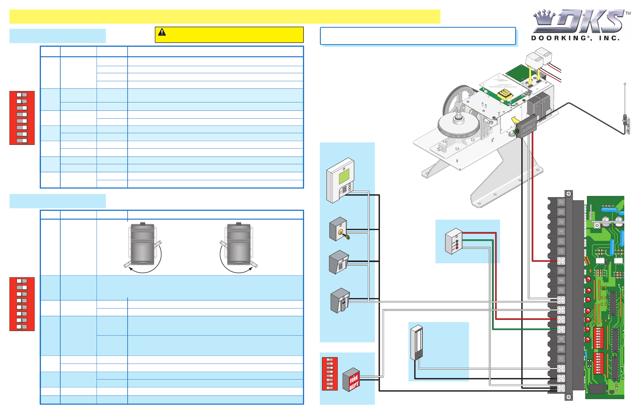
3-Wire Radio Receiver
Limited to 250 ma.
Power (24 Volt DC) and
logic output. Power is
shut off .5 sec. prior to
gate starting and remains
off while gate is opening
and in the open position.
Com
Relay
Red Open
Green Close
White Com
24
Vo
lt
Com
Com
Key Switch
Stand-Alone
Keypad
Stand-Alone
Card Reader
Telephone
Entry
Note: All stand-alone and
telephone entry devices must
use a separate power source.
20
19
18
17
16
15
14
13
12
11
10
9
8
7
6
5
4
3
2
1
NC
NO
1
ON
2
3
4
5
6
7
8
1
ON
2
3
4
5
6
7
8
Magnetic Lock
3-Button Station
DoorKing ONLY
SW 1
SW 2
SW 1, switch 3 must be ON.
#12 - Safety
Opening Device
Radio
Open
Access
Device
Open
Safety
Open
#11 - Access Control
Devices
Com
Com
SW 1
1
ON
2
3
4
5
6
7
8
Important:
Controls must be installed
a minimum of 10-feet from the gate or
installed in such a way that the person
using the control cannot come in
contact with the gate or gate operator.
24 Volt
1 amp max.
Coax Antenna Kit
P/N 1514-073
Antenna mounted
outside operator cover.
Convenience Open Radio
Receiver Note:
Wiring may differ.
See section 7 in the
Installation/Owner’s
manual for more info.
(2) Two 115 VAC
Convenience Outlets
On 6100 with Convenience
Open Model ONLY.
QUICKSTART “BASIC” GUIDELINES FOR MODEL 6050/6100 - DIP-SWITCH AND WIRING REFERENCE
120 Glasgow Avenue
Inglewood, California 90301
U.S.A.
Model 6050/6100 is intended for installation only on swing gates used for
vehicles.
Pedestrians must be supplied with a separate access opening.
For safety and installation instructions, please refer to the Installation/Owner’s manual.