Codelocks Hotel GuestLock 4000 Mortice Lock User Manual
Page 7
See page 9 for CL5010BB and page 10 for CL4020 and CL5020 Installation Instructions
13 FOR CL5010 LOCKS ONLY
.
Check that the spindle turns freely, and the latch retracts and
projects smoothly, with the alignment insert in place. If it is
tight, loosen the fixing bolts slightly and adjust the position
of the fixing plate until the spindle will turn freely. Tighten
the fixing bolts. Test the spindle again. Do not over-tighten
the bolts as this may cause the door to distort and affect the
lock function.
REMOVE THE ALIGNMENT INSERT.
14 FOR CL4010 LOCKS ONLY.
Remove the battery cover from the back plate, and remove
the battery pack. Apply the front plate over the spindle,
passing the latch support post through the latch and the
cable through the door. With both parts of the back plate
together place them over the spindle, pull the cable through,
and screw the fixing bolts through to the front plate.
7 FOR CL5010 LOCKS ONLY.
Screw the cable tube into the front plate, passing the cable through the
tube. For doors less than 45mm (1
25
/
32
”) thick screw the tube all the
way to the end of the thread. For doors more than 45mm (1
25
/
32
”) leave
an appropriate amount of thread showing to accommodate ring nut
.
Example: For a 60mm (2
3
/
8
”) thick door leave 15mm
(
3
/
5
”) of thread
showing.
8
Fit the self-adhesive gaskets to the front and back plates. The gaskets
provide friction against the door so that it is not necessary to over-
tighten the fixing bolts to provide stability.
9 FOR CL5010 LOCKS ONLY.
Remove the 4 socket head bolts from the back plate (2 are found under
the battery cover). This will release the inside fixing plate.
10
Cut the fixing bolts to correct length. Measured from beneath the bolt
head, the length should be the door thickness, plus approximately
15mm
(
3
/
5
”) to the nearest cutting point of the bolt.
N.B.
Always cut the bolts at one of the cutting points so as not to
damage a thread. Use the cutting edges of pliers to crimp strongly
several times around the selected cutting point. The surplus end
should break off quite easily.
11
Put the spindle into the latch with the spring on the front plate side of
the door.
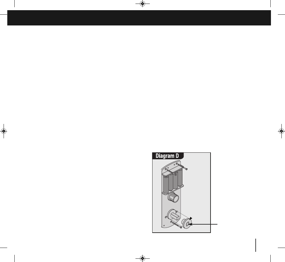
12 FOR CL5010 LOCKS ONLY.
Apply the front plate over the spindle, passing the cable tube through
the door and the latch support post through the latch. Place the fixing
plate over the cable tube and spindle. Screw the ring nut onto the
cable tube until finger tight. Fit the alignment insert over the spindle.
Screw the fixing bolts through to the front plate. (See diagram D).
Alignment insert
MUST be removed
before completing
installation.
7
Continued overleaf
CL5010 only
4000/5000 manual_Layout 1 14/01/2013 15:53 Page 7