Maintenance (continued) – CM-ET Series 653 User Manual
Page 10
Maintenance (Continued)
2. To replace the liftwheel or stripper,
completely disassemble the unit:
remove the chain (See REPLACING
LOAD CHAIN, page 7) and then
remove the brake nut, cotter pin and
spacer (19), free chaining knob (17),
lever (16), check washer (18), lever
ratchet (33), brake cover (14), friction
discs (12), ratchet (13), spring (6) and
friction hub (11). On the gear side,
remove the gear cover (8), gears (5)
and pinion (7). Remove snap ring and
liftwheel gear (23). Being careful not
to loose the rollers, remove the side
plate assembly (1). Slide the liftwheel
(22) out of the side plate (2), being
careful not to loose the rollers. The
stripper (4) can also be removed now.
Prior to re-assembly, check all parts
for excessive wear, cracks and
distortion. Replace parts as necessary
and then re-assemble the unit in
reverse to the order given above,
making sure to install the chain guide
rollers (10) and upper hook (25) and
pin (26). After assembly, install the
chain (See REPLACING LOAD CHAIN,
page 7) and then test the unit (See
TESTING, page 8).
3. The latch is secured to the hook
(upper and lower) by a rivet. To
remove the latch, it is necessary to
remove the head of the rivet by
grinding or drilling. For the
replacement of the latch, refer to
the paragraphs under assembly
instructions.
ASSEMBLY:
1. Thread the friction hub (11 ) onto the
pinion shaft (7 ) and assemble the
friction discs and the ratchet on the
friction hub (See Figure 8).
Place the spring (6) over the friction
hub and pinion. Place the brake cover
assembly (14) on the frame and thread
the lever ratchet (33) onto the pinion
shaft. Firmly seat the lever ratchet and
secure the brake cover assembly to the
frame using the four nuts (9).
Place the check washer (18) on the
pinion shaft so that there is 0.094 to
0.312 inches (2 to 8 mm) between the
edge of the check washer and the
raised stop on the lever ratchet hub
(See Figure 9).
Make sure the directional lever is in
the neutral (“N”) position and the
pawl, spring and shaft (20) are in the
lever assembly (16), attach the lever
assembly to the brake cover (14) using
the two locknuts, screw and
lockwasher (15). Place the free
chaining knob (17) on the lever
ratchet hub (33). Place the spacer (19)
over the pinion shaft, thread the
brake nut (19) onto the pinion shaft,
and firmly tighten the nut. Back off
the nut one to two flats and insert the
cotter pin (19). Bend the legs of the
cotter pin to secure.
2. When assembling the latch to the
hook, the end of the rivet must be
peened over. When peening over
rivet, only apply enough force to form
a head to retain the pin. Excessive
force will deform the latch and make
the latch inoperable.
3. When assembling the gears, they
must be orientated with the timing
marks aligned (See Figure 10).
REPLACING LOAD CHAIN
To replace the load chain, remove the
lower hook block and chain stop from
the chain. Move the directional lever to
the neutral “N” and pull the old chain
out of the hoist. Feed a length of soft
wire through one side of the chain
guide roller and over the liftwheel until
it comes out on the other side of the
chain guide roller. Attach the wire to
the end of the new chain. Position the
chain so that the first link to enter the
chain guide roller will be an upstanding
link and the welds on all upstanding
links will be away from the liftwheel.
Pull on the wire until the chain engages
the liftwheel. Turn the free chaining
knob, while pulling on the wire, until
the chain comes out of the chain guide
roller. Pull the chain through and
remove the wire. On the 3/4, 1, 1 1/2, 2
and 3 Ton units attach the lower hook
block to the chain that is directly below
the upper hook. On the 6 Ton unit,
reeve the chain as shown below. Attach
the chain stop to the other end of the
chain.
RECOMMENDED SPARE PARTS
To insure continued operation, it is
recommended that two friction
discs (12) for each Series 653 lever
hoist in service, be kept on hand
at all times to replace friction
washers that are worn,contamin-
ated or glazed.
7
Chain welds
away from
Liftwheel
Liftwheel
Chain guide
roller-Chain
Stop Side
Stripper
Chain guide
roller-Lower
Hook Side
Lower
Hook
Block
Chain Stop-
Position as
Shown
Ratchet
Friction
Hub
Friction Disc
Pawl
Ratchet
Pawl
Figure 8 - Brake Assembly
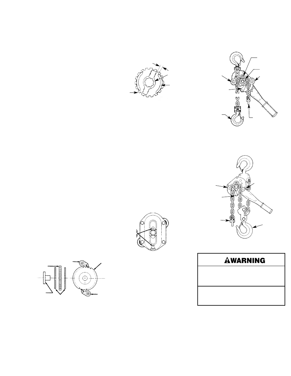
Raised
Stop
Lever
Ratchet
Check
Washer
Figure 9 - Position of Check Washer
Timing
Marks
Figure 10 - Gear Timing
Chain Installation-3/4, 1, 1½, 2 and 3 Ton
0.094 to 0.312 IN.
(2 to 8mm)
Alterations or modifications of equipment and
use of any parts other than Series 653 repair
parts can lead to dangerous operation and
injury.
TO AVOID INJURY:
Do not alter or modify equipment. Do use only
Series 653 provided replacement parts.
Chain Guide
Roller-End
Ring Side
Chain Guide
Roller-Hook
Side
Figure 11. Reeving - 6 Ton
Stripper
End Ring
Lower
Hook
Block