CM-ET Lodestar User Manual
Page 16
4. Turn adjusting nuts clockwise gaging the air gap at
both ends.
5. Replace cover, reconnect the power and check .
operation.
LIMIT SWITCHES
If limit switch operation has been checked as described on
page 7 and is not operating correctly or is not automatically
stopping the hook at a desired position, proceed as follows:
1. Disconnect hoist from power supply.
2. Remove back frame cover, see Figure 13.
3. The position of upper and lower limit switches are indi-
cated on the fiber insulator.
4. Loosen the screws to permit guide plate to be moved
out of engagement with the traveling nuts, refer to Fig-
ures 18 and 19.
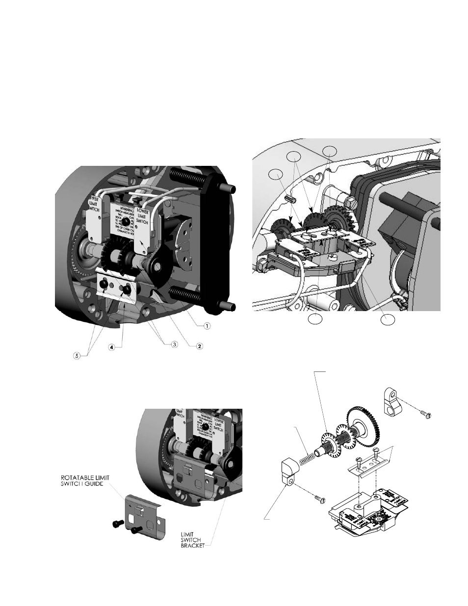
Figure 18. Limit Switches, Models B, C & F
1. Limit switch sub-assy 4. Guide plate
2. Limit switch shaft 5. Screws
3. Traveling nuts
Figure 18A. Rotatable Limit Switches, Models B, C & F
1. Disconnect the hoist from the power supply system.
2. Refer to th exploded views and remove the back frame
cover from the hoist.
3. Remove and discard the limit switch guide plate and .
attaching screws.
4. Refer to Figure 18A and assemble the rotatable limit switch
guide from the kit to the limit switch bracket (spring back the
guide tab to engage the slots in the traveling nuts) using the
screws provided. Securely tighten the screws.
5. Reset the limit switches. Spring back the guide tab to allow
the traveling nuts to be rotated to the desired position.
Figure 19. Limit Switches, Models J, L, R, LL & RR
1. Limit switch sub-assy 4. Guide plate
2. Limit switch shaft 5. Screws
3. Traveling nuts
Figure 19A. Industrial Limit Switches, Models J, L, R, LL
& RR
12
2
1
5
4
3
LIMIT SWITCH
SHAFT SPRING
REPLACE
LIMIT SWITCH
SHAFT BEARING
LIMIT SWITCH
GUIDE PLATE
AND ATTACHING
SCREWS-
REMOVE AND
DISCARD
LIMIT SWITCH
SHAFT ASSEMBLY