Connecting your am 81 – Clock Audio AM 81 User Manual
Page 6
06
Connecting your AM 81
1 Power
The mains power is connected via the fused IEC
connector on the rear panel, power source should be
220vAC~50Hz.
2 Microphone Inputs
Microphone Inputs: The 8x Microphone Inputs are
provided via 3pin XLR-Female type connectors.
Inputs may be configured to accept both Condenser
type microphones, the mixer providing a +48v Phantom
Power facility or Dynamic Balanced type microphones.
If connecting external equipment other than
microphones, these devices where possible, should be
connected at Microphone Signal Output level, to prevent
overdriving/distortion of the input signal.
3 Master Output
The Master Output is used to connect the mixer to the
system amplifier, processor or recording device, via
balanced XLR~M connector.
Internal settings inside the mixer can be configured
to provide different output configurations, including
Microphone or Line Level Output options.
4 Pre-Amplifier Outputs
Pre-Amplifier Outputs are provided via mono Phono type
connectors, the level from each output is 550mv 3.3K
ohms. These outputs can be used for recording individual
or groups of channels.
Operation of the Pre-Amplifier outputs can be configured
to operate “Before” or “Behind” the gate control.
If set to “Before” the output from the Pre-Amplifier Output
(Ch1~8) will output a signal, regardless of if the channel
gate is open or closed.
If set to the “Behind” option the output from the
Pre-Amplifier is controlled by the individual gate control
of the channel, when the gate is open the audio signal is
passed via the relevant Pre-Amplifier Output connector
(Ch1~8), and when the gate is closed the audio signal
is cut off.
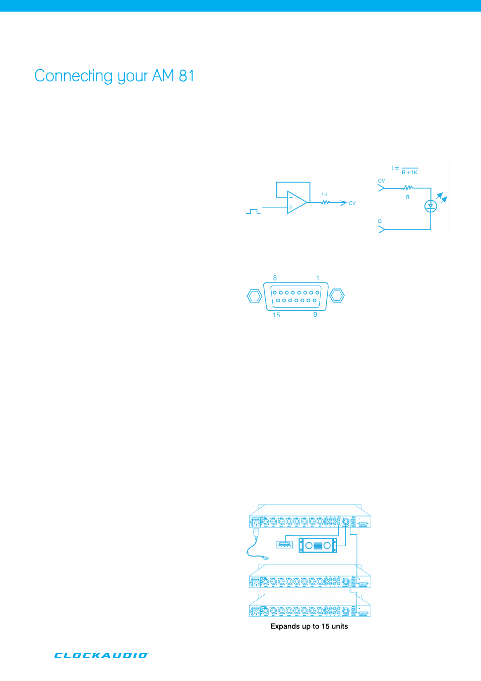
5 External Control Function
This remote control feature is provided via a 15pin D Type
connector.
Pins 1~8 control the gain level for each channel, as well
as providing switched voltage free outputs for controlling
external relays and devices or LED’s.
The following references can be used.
6 Expansion Options
If using the AM 81 as part of a larger system the ability to link
units together is an option, units can “daisy chain” together
via multi pole “Link In” and “Link Out” connections.
Up to 15 units may be configured in this way to
provide a fully functioning system with a capacity of up to
120 microphones.
Inner Output
Connect to LED
1 Channel 8 ON/OFF controlling signal
2 Channel 7 ON/OFF controlling signal
3 Channel 6 ON/OFF controlling signal
4 Channel 5 ON/OFF controlling signal
5 Channel 4 ON/OFF controlling signal
6 Channel 3 ON/OFF controlling signal
7 Channel 2 ON/OFF controlling signal
8 Channel 1 ON/OFF controlling signal
9 Ground 10. Ground 11. NC 12. NC 13. NC 14. NC 15.
PIN Instruction for External Controller Output Port: