Final checklist, Technical specification, Security and safety – Clock Audio AM 81 User Manual
Page 10: Danger
10
Final Checklist
Once all individual settings and configurations have been
made to the internal control of the AM 81 it is recommended
the following procedure is followed when connecting
and commissioning the system, it may be an idea to have
someone to assist you when carrying out this procedure.
1
Turn down the gain levels of the amplifier or host
equipment or disconnect the mixer unit from the
amplifier or host equipment.
2
Reduce the gain level of the Master and Input Channels
(1~8) on the mixer front panel to the minimum position,
also reduce the level of any connected amplifier if
still linked.
3
Connect the power lead and switch on the mixer, the
unit will automatically check the status for each
channel.
NB 48v Phantom Power is provided for each microphone
channel, the wiring for each input must be balanced,
please ensure correct configuration prior to
installation.
4
Set the input gain control for the required channel to
approx 9 o’clock, if the channels are each set up
with different input sensitivity adjust individually to
provide an equal gain level.
5
Firstly test the channels not configured as priority
channels.
Using the installed microphones speak clearly into the
individual microphone, check both the audio output
signal via the headphone socket and the visual channel
indicator on the front panel of the mixer.
6
Secondly test the channels set up with priority.
Priority channels are active simultaneously, speak into
the microphone connected to the priority channel and
check the visual indicator on the front panel.
Next speak into the microphone of the priority channel
whilst a colleague is speaking into a non priority channel,
the level of the no priority channel should reduce/
attenuate by up to -40dB.
7
Once satisfied with the above test procedure, set the
mixer to the desired operational levels and increase the
levels or re-connect the host amplifier/equipment.
In many typical applications the Chairman’s microphone
position is usually set up with priority, in this scenario please
do not locate the chairmans microphone close to or facing
any installed loudspeakers. Because this microphone is
likely to be active for long periods we advise taking the
above guidance to avoid any potential for the microphone
picking up the loudspeaker signal and preventing the
opportunity of any feedback issues.
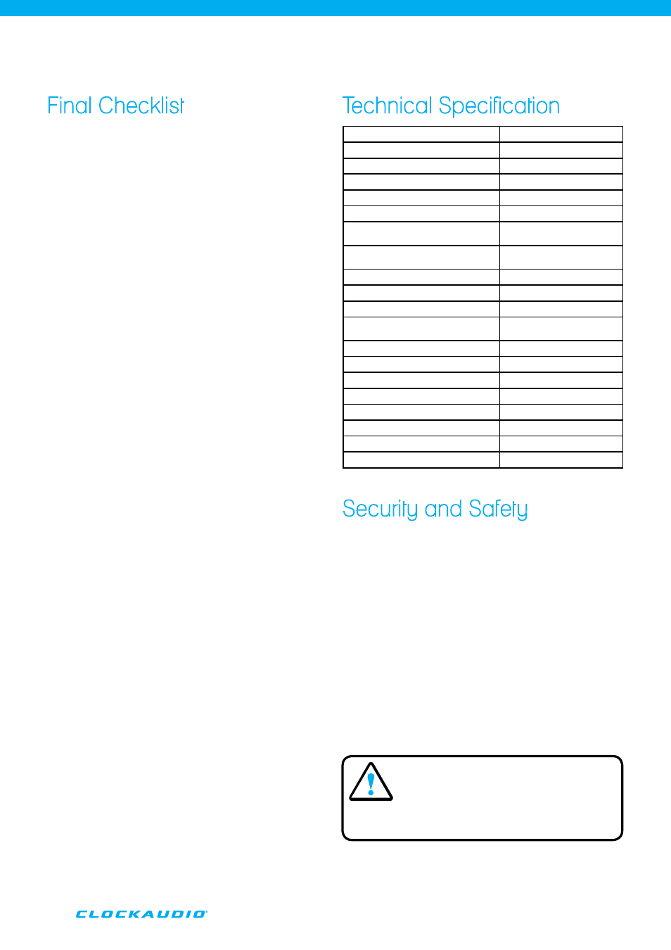
Technical Specification
Security and Safety
•
To prevent the potential for electric shock please take
extreme care in making any adjustments or altering any
settings.
•
Whilst the unit is DC powered ensure that no contact is
made to the Power Supply or DC Power Jack.
•
Please check the Supply Voltage is correct prior to plug
in and switch on.
•
When configuring internal settings please use an
electrically insulated tool or plastic implement to operate
any switch settings or adjust any level controls.
•
When installed make sure the unit is earthed/grounded
correctly.
•
Do not use the mixer in conditions of extreme dust or
extreme humidity.
Input Impedance
MIC 4300W, AUX 50KW
Output Impedance (balanced)
MIC 15KW, Line 220W
Output Impedance (unbalanced)
1KW
Pre-Amplifier Output Impedance
3.3KW
Max Input Level
MIC -18dBv, AUX 6dBv
Max Output Level (Balanced)
MIC -18dBv, Line 21.5dBv
Standard Input Level (Balanced)
MIC -28dBv, Unbalanced
AUX 2.5dBv
Pre-Amplifier Output Level
(Balanced)
MIC -25dBv, Line 0dB
Pre-Amplifier Output Level
-4.4dBv
Max Gain
62dB
Frequency Response
20Hz~20KHz
Noise
All channels with the max
gain position (220W) -85dB
THD+N
≤0.5%
S/N
75dB
Phantom Power
+48v
Controlling Output Voltage
5v
Power Voltage
AC220v
Current Consumption
25W
Dimension
48(H) x 430(W) x 221(D)mm
Weight
3.2kg
DANGER!
PLEASE ENSURE THE POWER SUPPLY
IS SWITCHED OFF BEFORE REMOVING
THE TOP COVER TO MAKE SYSTEM
ADJUSTMENTS.
As part of a continuous product improvement programme, we
reserve the right to alter specifications without prior notice.