Page 5 mr88 front panel – Clock Audio MR 88 User Manual
Page 5
Page 5
MR88 Front Panel
Power
Monitor
Output Level
Controls
Selected Channel
-20
1
-10
2
-6
3
-3
4
0
5
+3
6
7
8
+6 O/L
Channel
Function
CL OCKAUDI O
MR88
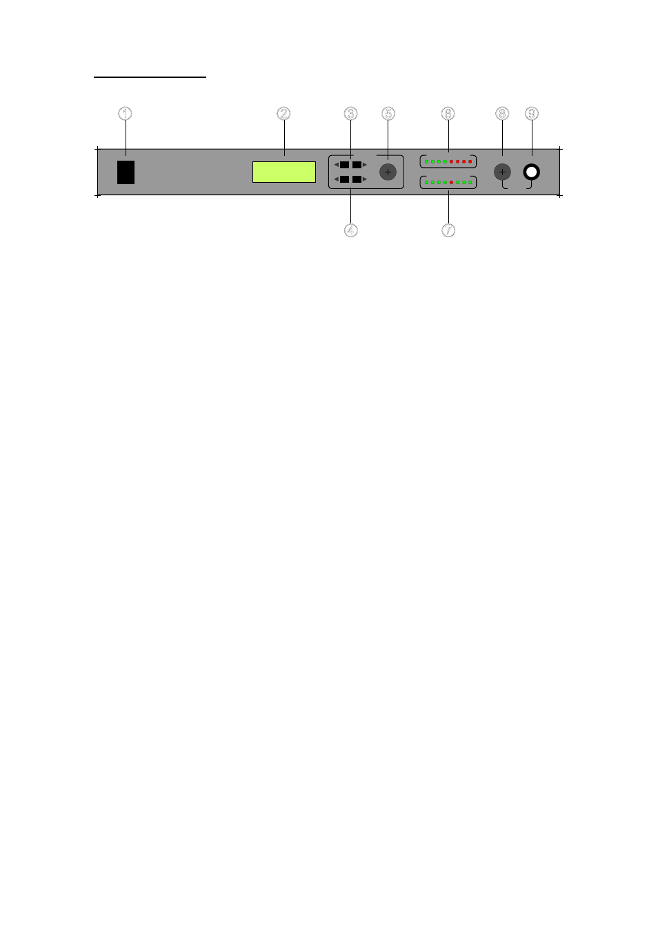
1) Power Switch.
2) Display. Displays selected channel/function and settings for each.
3) Channel Buttons. Select between System settings, Output channels A
and B, and Input Channels 1-8.
4) Function Buttons. Selects set-up functions for each channel.
5) Rotary Control. Adjusts the settings on each function.
6) LED Level meter Indicates peak output level of the selected channel in
dB.
7) The Selected Channel LEDs indicates which microphone is currently
in use and which other microphones are being "locked out"
(attenuated). Green is active and Red is locked out.
8) Monitor Volume Control. Adjusts headphone amplifier volume.
9) Headphone Output. 1/4" TRS jack. Monitors the selected channel.