Clock Audio SM 80S User Manual
Sm 80
P R O F
A low p
E S S I O N A L M I
profile throu
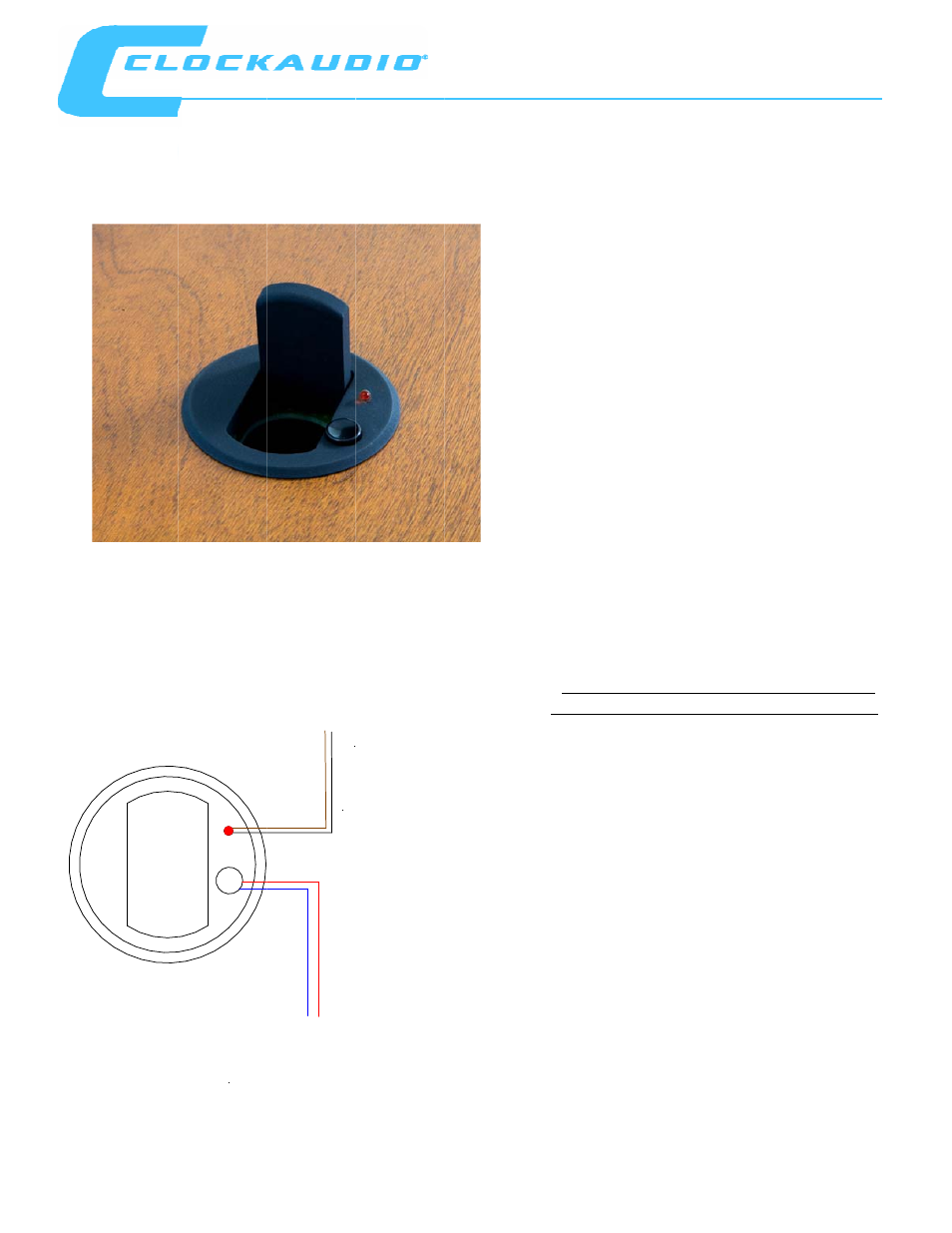
Conne
Red Sw
Blue S
C R O P H O N E S
gh table sho
co
Th
5v
de
T
B
B
ect to logic box
witch PTT +
Switch -
Y S T E M S
ock mount m
onnector wh
www.c
here is a jumpe
v/12v or 24v d
efalt setting is
To DC Power s
Brown LED +
Black LED -
x for switching
microphone
hen closed.
clockaudio.co
•
•
•
•
•
•
•
•
er/selector for
c operation.
24V
upply
base fitted
om
• Designed
• Low profi
base.
• Includes a
to be use
• Built in sh
bound no
• Fitted wit
• Red LED t
• Housing
• Fitted wi
block su
WIRING
HALO-RF
PIN 2 =
PIN 4 =
Max. V
Forw
Connect
supply an
switc
with a flip c
for remote s
ile table mou
a concealed f
d for other p
hock mount to
oise.
th latching sw
to confirm sta
a 5 Pin Fema
ith 5 way so
pplied with
G INSTRUCT
MICROPHO
PIN 1 =
= LED – (Re
PIN 3 = P
= LED + (Re
PIN 5 = P
Voltage for
ward current
t Pin 2 and P
nd to Logic
h from red t
SM 80
cover to con
switching.
nted microph
flap to allow t
urposes.
o eliminate s
witch.
atus.
le XLR.
ocket termin
fixing screw
ION FOR BI
ONES WITH
Ground
ed) or LED +
PHASE –
ed) or LED –
PHASE +
LED = 12V
t max = 30m
Pin 4 to a 12
box. Revers
to green illu
0S
nceal the
hone
the table
urface
nal
ws
I-COLOUR
5 PIN XLR
+ (Green)
– (Green)
dc
mA
2V dc powe
se polarity t
umination
r
to