Maximum trim, Inertia compensation, Operating – Cleveland Motion Controls WebPro Motor Powered Unwind Tension Controller MWP – 12662 - 1 REV BA User Manual
Page 20
AO-70172
19
Revision BA
WebPro Motor Powered Unwind Tension Controller
To simplify the tuning there are five factory set PI values. One of these values should be suitable for most
applications. If it is found necessary to apply different PI values, select Custom and starting from PI
values that gave stable but sluggish operation, reduce the P band % value and reduce the I time value
until the desired performance is achieved. Remember to press the CONFIRM key before exiting the
Product Parameter or the Adjust PI stability menus in order to implement and save any changes.
The five preset PI values are:
very slow
slow
medium
fast
very fast
Proportional
band
2000%
1200%
800%
500%
200%
Integral time
20 sec
12 sec
8 sec
5 sec
2 sec
Maximum Trim
Set this item to a value which gives best overall performance. Too large a value may apply too much
correction and make the system unstable. The value should be sufficient to compensate for tension
disturbances, diameter calculator errors and any other errors. Extensible materials may require a trim
value higher than more rigid materials. As a guide set this item to 10%.
Inertia Compensation
While accelerating or decelerating the machine at the normal maximum rate observe the measured
tension bar graph and the desired tension set point triangle. If these differ by more than 10% adjust the
Inertia Time Constant and the Coefficient to compensate for any increase in tension while accelerating or
decrease in tension while decelerating. The Inertia Time Constant determines the rate of correction; the
Coefficient determines the amount of correction.
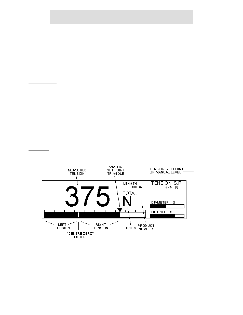
Operating
A typical Control screen is shown below.
The manual feature is only available in Unwind Brake mode. The taper feature does not operate.
The Auto Tension set point may be set with the numeric keys followed by ENTER or by the +/- keys.
The analog tension set point triangle is only visible when the Controller is in Auto control. The measured
tension analog bar graph and the set point triangle should coincide when in control.