Cleveland Motion Controls DIN Rail Amplifier MWI-13261 Ultra Series Isolated REV BA User Manual
Page 25
MAN-13261
R
EV
BA
DIN
R
AIL
A
MPLIFIER
,
MWI-13261
U
LTRA
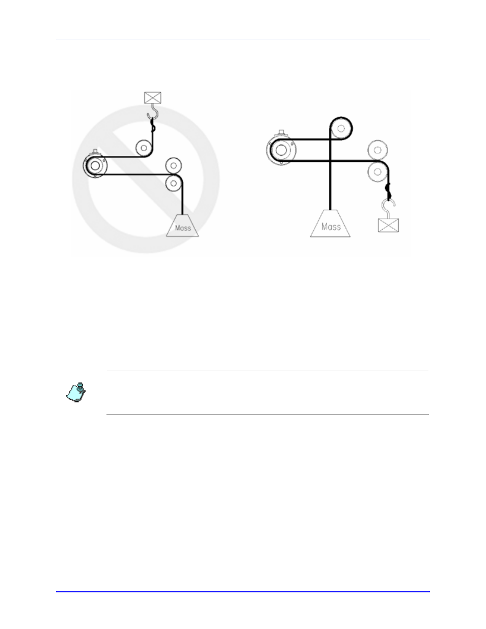
Examples of Force Loss due to Friction at Driven Roll
In this example, only a fraction of the test force is
transferred to the transducer due to drag from the
driven roll.
In this example, by rearranging the anchor point
and the force location as well as utilizing the idle
roll, the frictional losses are minimized.
3.6 A
PPLYING
F
ORCE TO
T
RANSDUCERS
The application of an accurate calibration force can be a challenge. Keep the following points in mind:
• Allow the transducer and amplifier to reach thermal equilibrium before conducting
calibration. Ideally, the temperature should reflect the expected operating conditions.
• With very low force transducers, consider that connecting a test mass will involve some
finite cord mass.
When conducting a calibration that involves a large mass, it is often practical to use a series of smaller masses
added in succession. Consider performing an initial Zero and Gain adjustment when the first 20% of the
weights have been applied. By performing the calibration using this method, the Zero and Gain adjustments
can be made approximately correct earlier in the calibration effort (before many weights have been handled).
When the full calibration load is applied, there is a better chance that only minor adjustments will be needed.
3.7 A
DJUSTMENT
T
OOLS
Using the correct tools simplifies the setup process and necessary adjustments. Keep the following points in mind:
• The Ultra Series DIN Rail amplifier utilizes two different potentiometer styles. The Gain
and Zero adjustments located on the front of the amplifier are more likely to be adjusted over
the life of the product. For that reason they are physically larger and more robust. The
industry standard “pot tweaker” is an ideal tool. The adjustment tool should have dimension
on the order of 0.5mm (.020 inches) blade thickness and be 2.5 mm wide (0.1inches).
• The adjustments that are usually made only once during initial setup are located behind a
snap on access cover. This less obvious location helps to discourage alteration by
unqualified persons. The infrequent adjustment of these potentiometers has warranted the
use of smaller surface mount technology devices (SMT). A correspondingly narrower blade
is needed (1.4 mm wide, 0.055”inches).
• When changing the internal jumper-switch settings, it is always advisable to change the
settings with the 24 VDC power removed. If this is not possible, it becomes particularly
P
AGE
25
OF
30