12 w – Cleveland Motion Controls DIN Rail Amplifier MWI-13261 Ultra Series Isolated REV BA User Manual
Page 15
MAN-13261
R
EV
BA
DIN
R
AIL
A
MPLIFIER
,
MWI-13261
U
LTRA
2.12 W
IRING
Most start-up problems are the result of mis-wiring or failure to reference the detailed information in this manual.
While a convenient basic wiring diagram can be found printed on the side label of the amplifier case, the diagram is
intended only as a helpful guide when checking field wiring. Additional information details can be found in the
subsequent sections of this manual and should be referenced before actual installation begins.
2.12.1 W
IRING TERMINATION
Terminal(s)
Conductor Size
Insulation Strip Length
Torque
Notes
All
1.5mm
2
/16 AWG
0.75mm
2
/18 AWG
0.5mm
2
/20 AWG
7 mm ( 0.28” )
7 mm ( 0.28” )
7 mm ( 0.28” )
0.5 Nm / 4.4 lb.-in.
0.5 Nm / 4.4 lb.-in.
0.5 Nm / 4.4 lb.-in.
One wire this size per terminal
Up to two wires this size per terminal
Up to two wires this size per terminal
2.12.2 T
RANSDUCER
W
IRING
1
2
5
4
3
6
7
8
4
BRN
3
2
1
BLU
BLK
WHT
LEFT XDCR
2
3
6
5
4
8
7
WHT
BLU
BRN
BLK
RIGHT XDCR
1
3
1
4
2
C
T
C
T
C
T
T
C
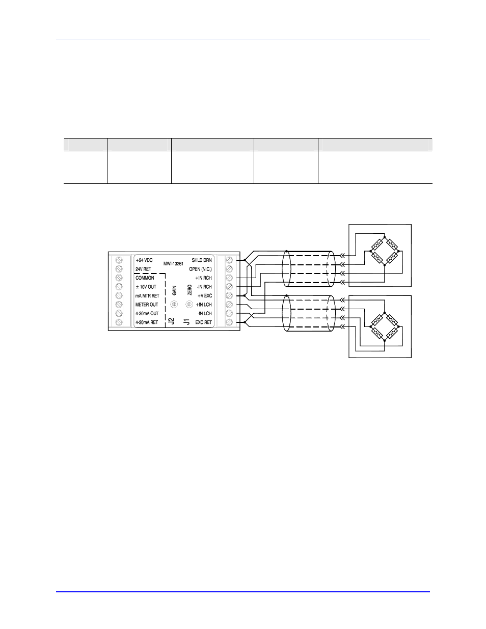
Figure 5 - Full-bridge Transducer Wiring
The successful amplification of low level signals from strain gage transducers requires particular attention to wiring
practices to avoid signal degradation in the industrial environment. Degradation can result from AC noise pickup
and/or DC errors. Refer to the following guidelines to identify measures that may help retain signal quality:
•
Use Ultra Series shielded transducer cables to reduce pickup of noise through electrostatic coupling.
•
Route cables away from sources of electrical interference (motor wiring, contactors, etc).
•
Connect the shield drain wire at one end only to discourage shield currents.
•
Optimum high frequency grounding requires low inductance connections that are enhanced with short
conductors or planar ground conductors (wide ground braids).
•
Do not pre-tin the stranded wires inserted into the pluggable connector.
•
A stable connection relies on the springy nature of stranded conductors to ensure a low contact
resistance despite thermal cycling and airborne impurities.
•
Avoid temperature extremes or gradients where electrical connections are made between different
metals. Connections can cause thermocouple voltages to be generated, which then become
superimposed on transducer signals.
•
In severe cases, additional shielding may be required in the form of either external flexible braided
shields or running the field wiring wires inside metallic conduit.
P
AGE
15
OF
30