13 t – Cleveland Motion Controls DIN Rail Amplifier MWI-13262 Ultra Series Non-Isolated REV BA User Manual
Page 15
MAN-13262
R
EV
BA
DIN
R
AIL
A
MPLIFIER
,
MWI-13262
U
LTRA
2.13 T
HE
P
OWER
S
UPPLY
For best performance a regulated power supply should be used with the Ultra Series DIN Rail amplifier. It is
important that you pay particular attention to the power supply for susceptibility to the effects of conducted and
radiated energy from noise sources. Every effort should be made to provide stable voltage to the amplifier using
correct wiring practices and filters. To protect against circuit damage, include a 0.38 Amp fuse in the power supply
output lead to each amplifier in case of amplifier or power supply malfunction.
2.13.1 P
OWER
W
IRING DIAGRAM
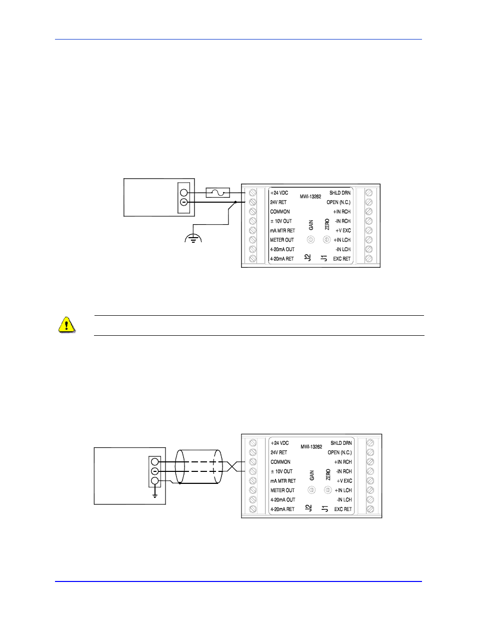
The 0.38 A fuse in the +24VDC power lead is required for protection of the amplifier in the event of amplifier or
power supply malfunction.
8
7
5
6
3
4
2
1
1
2
3
4
6
5
7
8
+
24 V
0 V
FUSE
24 Vdc
POWER
SUPPLY
Figure 6 - Wiring diagram for use with 24 VDC power supply
The power source for the power supply shall be fused at the proper rating to prevent over current in
the supply leads due to a power supply failure.
2.13.2 O
UTPUT WIRING
The load in this connection may be an indicator, recorder, data acquisition device or the analog input terminals of a
control device such as a DC drive or a programmable logic controller. The output signal at this terminal is
undamped and is the output terminal that provides that fastest response to changes in the transducer (load-cell) load.
Note that the cable’s shield drain wire should be connected at only one end, preferably at the “receiving end”.
8
7
1
2
3
5
6
4
2
1
6
4
3
5
7
8
SHIELD GND
RESISTANCE
5000 OHM MIN
+ / - 10V LOAD
+
Figure 7 - Output Wiring, +/- 10V Analog
P
AGE
15
OF
26