Mating connectors for transducers, Intrinsically safe transducers, Temperature compensation – Cleveland Motion Controls Classic Tension Transducers SC-EP REV GA User Manual
Page 9: Troubleshooting, Excessive output signal with no load, Low output signal, Output signal fails to increase with added load, Wrong polarity of output signal, 2 intrinsically safe transducers, 4 temperature compensation
Cleveland-Kidder Transducers; EC, ECM, SC, SCM & SC-EP
A800-7438 Rev GA
P
AGE
9
OF
10
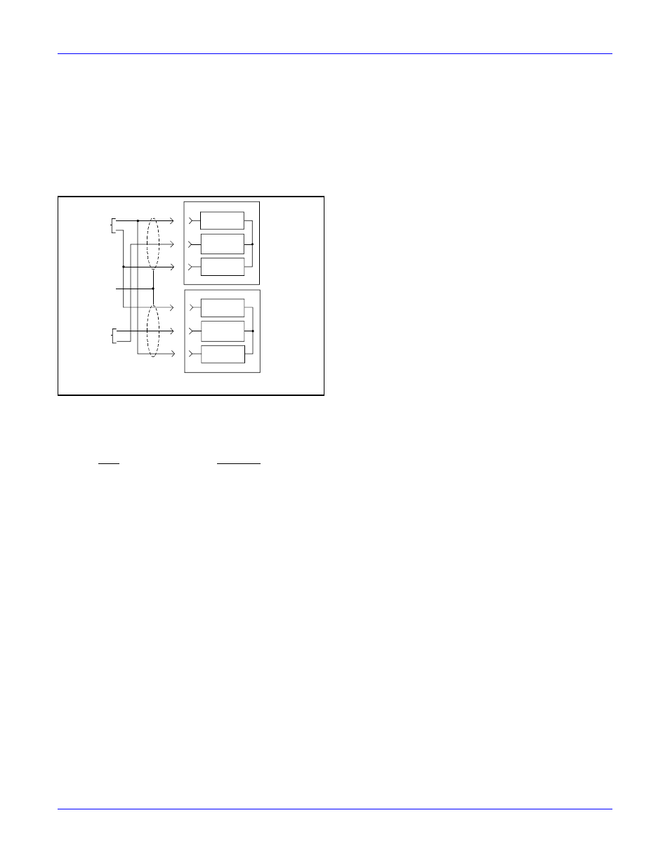
Figure 6 is for reference only for use with a full
bridge transducer configuration. Many of the
Cleveland-Kidder indicators and controllers use
only half bridge transducer inputs and then sum
the two transducer signals internally. See the
applicable installation wiring diagrams for the
tension indicator or controller.
Figure 6
3.1 MATING CONNECTORS FOR TRANSDUCERS
USE
CMC
P/N
Mating Straight Connector,
Boot and Clamp Kit
MO-09854
Mating 90
○
Angle Connector,
Boot and Clamp Kit
MO-09855
3.2 INTRINSICALLY SAFE TRANSDUCERS
These transducers are intrinsically safe only when
they are part of a complete intrinsically safe
system using the TIX-1 tension indicator or wired
per CMC control drawings.
For transducers utilizing a 5.6 VDC (±2.8 VDC)
excitation voltage refer to CMC Control Drawing
A800-42273. For transducers utilizing a +5VDC
excitation voltage refer to CMC Control Drawing
A800-42281.
Barrier block assemblies and/or the individual
barrier blocks may be purchased from CMC.
Please contact CMC for part numbers and pricing.
4 TEMPERATURE
COMPENSATION
The transducers are supplied with a temperature
compensation network which is in series with the
output signal lead. The compensation circuit is
designed to be used with a tension amplifier
which has an input impedance of 10K Ohms when
a pair of transducers connected as a full bridge is
used. If only one transducer is used, the tension
amplifier impedance should be 5K Ohms. If other
than the input impedances given above are used,
drift will occur in the tension amplifier output
when the transducer temperature changes.
5 TROUBLESHOOTING
5.1 EXCESSIVE OUTPUT SIGNAL WITH NO LOAD
There may be a high degree of misalignment of
the transducers causing a severe pre-load.
or
The sensing guide roll assembly may be
excessively heavy. The sensing guide roll should
not weigh more than ½ the maximum working
force of the transducers in most cases.
5.2 LOW OUTPUT SIGNAL
The transducer may have too large a maximum
working force for the application. Replace with a
lower maximum working force transducer or
increase web wrap angle.
5.3 OUTPUT SIGNAL FAILS TO INCREASE WITH
ADDED LOAD
The transducers are overloaded and are hitting
their stops. Replace the transducers with ones
having a higher maximum working force or
reduce the load. This may be accomplished by
reducing the web wrap angle and/or using a
lighter sensing roll.
5.4 WRONG POLARITY OF OUTPUT SIGNAL
Transducers may have been incorrectly oriented.
Rotate them 180 degrees. If rotation is impossible,
interchange the transducer leads as instructed in
the tension indicator or controller manual.
EXCITATION
VOLTAGE
OUTPUT
SIGNAL
SHIELD
BLK
WHT
NO. 1
TRANSDUCER
RED
BLK
WHT
RED
B
A
C
B
A
C
NO. 2
TRANSDUCER
TENSION
GAGE
TEMPERATURE
COMPENSATION
NETW ORK
COMPRESSION
GAGE
TENSION
GAGE
TEMPERATURE
COMPENSATION
NETWORK
COMPRESSION
GAGE
( — )
( + )
( — )
( + )
WIRING DIAGRAM FOR TRANSDUCERS