Avocent 416 User Manual
Page 18
12
AutoView 424 Installer/User Guide
To install an AutoView 424 switch:
1. Power down all computers that will be part of your AutoView 424 system.
2. Plug your VGA monitor cable into the port labeled
on the back of your
AutoView 424. For Sun support, plug your Sun connector into the port
labeled SUN and for PS/2 peripherals, plug your PS/2 keyboard cable and
your PS/2 mouse cable into the ports labeled
and respectively.
NOTE: A PS/2 keyboard will not function if a Sun keyboard is attached. However, you may
use a PS/2 mouse with a Sun keyboard.
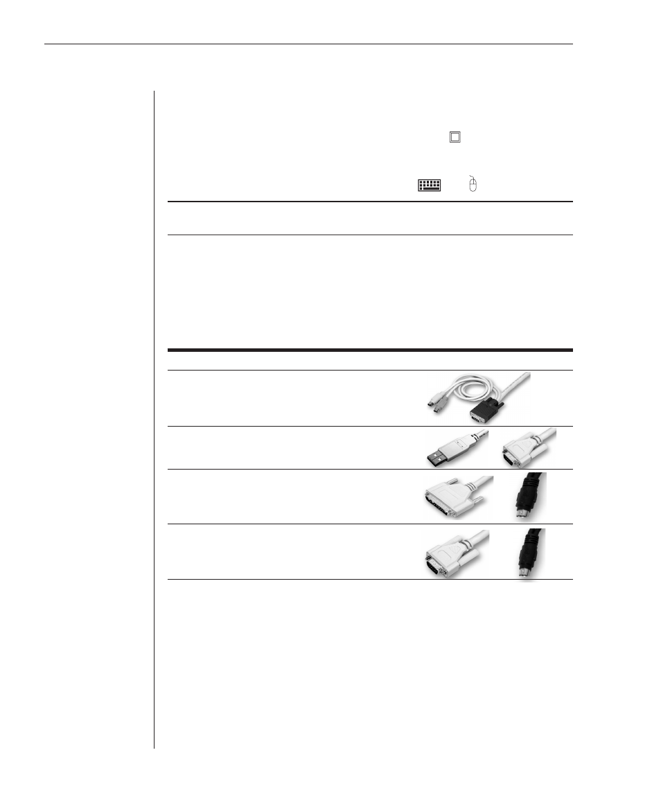
3. Locate the input cable appropriate to the computer you are connecting.
AutoView 424 cable types are identified below. Plug this cable into any
numbered channel port on the rear of the AutoView 424. The other end of
the input cable will have up to three connectors depending on type. Plug
these connectors into the matching ports on your computer.
AutoView 424 Cable Types
Cable
Description
Length
CIFCM-4 PS/2
only/VGA
4
ft
CIFCM-8 PS/2
only/VGA
8
ft
CIFCM-15 PS/2
only/VGA
15
ft
CIFCM-30 PS/2
only/VGA
30
ft
CUSBM-4 USB/VGA
4
ft
CUSBM-8 USB/VGA
8
ft
CUSBM-12 USB/VGA
12
ft
CWSNM-4
SUN Kbd/Mouse 13W3
4 ft
CWSNM-8
SUN Kbd/Mouse 13W3
8 ft
CWSNM-15
SUN Kbd/Mouse 13W3
15 ft
CWSNM-30
SUN Kbd/Mouse 13W3
30 ft
CVSNM-4 SUN
Kbd/Mouse
VGA 4
ft
CVSNM-8
SUN Kbd/Mouse VGA
8 ft
CVSNM-15 SUN
Kbd/Mouse
VGA 15
ft
CVSNM-30 SUN
Kbd/Mouse
VGA 30
ft
4. Locate your next input cable. Repeat step 3 until all computers are properly
attached to the AutoView 424.
5. Locate the power cord that came with your AutoView 424 unit and plug
it into the IEC power connector on the AutoView 424. Make sure that the
power switch is off, then plug the other end of the power cord into an
appropriate AC wall outlet. This outlet must be near the equipment and
easily accessible to allow for unplugging prior to any servicing of the unit.
6.
Power up your AutoView 424 unit first, then power up all attached computers.