Warning – Kolpin 4433 – Universal Mount Stereo Console User Manual
Page 2
4) Utilizing a 9/32” drill bit, carefully drill out the your hole locations
as indicated in Image “D”.
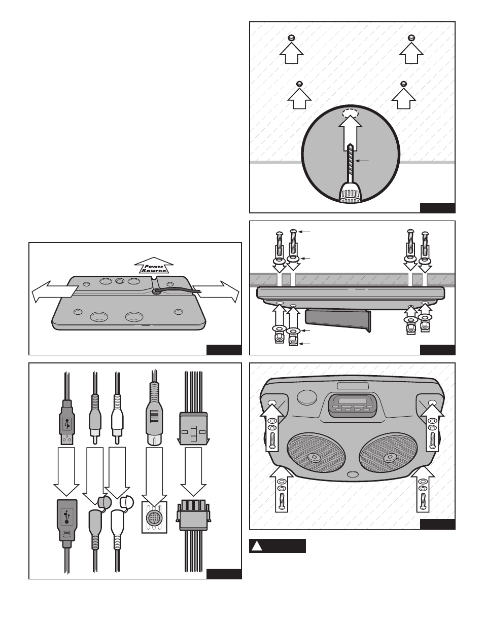
5) On the exterior of the top half of the console, you will see three
channels that lead from where the power line exits the unit as
indicated in Image “E”. Before final installation, be certain to
choose one of these channels to run the power line (left, rear or
right) based upon the location of your power source.
6) Mount the top half of the console to your mounting surface using
the supplied M6 x 60mm lg. button head cap screws, 6mm
sealing washers, M6 x 25mm O.D. fender washers and M6
nylock nut as indicated in Image “F”. Do not overtighten.
7) Assemble the two halves of the console, making certain not to
damage any wires. Do so by carefully reconnecting the USB
plug, red and white RCA jacks, DIN connector and speaker plug
as indicated in Image “G”.
8) Finish mounting the console by reconnecting the two halves
utilizing the four M6 x 35mm screws, lock washers and flat
washers retained from “Step 1”. Do not overtighten.
9) Carefully connect the power line to an approved 12 power source.
Once you have ran the power line, use the supplied cable ties to
secure the cord.
Failure to follow these installation
instructions completely may void any
warrantable components and result in property damage or
personal injury. NEVER operate or transport ATV with
unsecured cargo.
For additional assistance, please contact our customer service department at:
Kolpin Outdoors, Inc. | 205 N. Depot Street | Fox Lake, WI 53933 | 1.877.956.5746 | [email protected]
!
WARNING
2
1
3
4
Drill
9/32”
Drill Bit
Image D
Mounting Surface Cross Section
M6 x 60mm
Button Head Cap Screw
M6 x 20mm O.D.
Sealing Washer
1
4
2
3
M6 x 25mm
Fender Washer
M6 Nylock Nut
Image F
3
4
1
2
1
2
Image H
Power
Source
Power
Source
Image E
Red RCA Jack
USB Plug
White RCA Jack
DIN Connector
Speaker Plug
View from Rear of
Black Box
Use Plug Marked
“FRONT”
Image G