Silver series, Installation instructions – KING Silver Series User Manual
Page 5
(714) 891-0008 • www.kinginstrumentco.com
When it comes to flow...we’re instrumental.
5
Silver Series
Installation Instructions
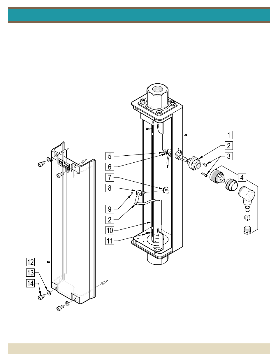
silver series asseMbly with alarM
parts list:
1. Meter Assembly
2. Alarm Switch Assembly
3. Alarm Switch Assembly Screw
4. Alarm Connector Plug
5. Ground Nut
6. Ground Lock Washer
7. Alarm Switch Housing Wing Nut
8. Alarm Switch Housing
9. Alarm Switch Housing Set Screw
10. Alarm Scale Plate
11. Alarm Scale Plate Screw
12. Shield
13. Shield Flat Washer
14. Shield Screw
1) Inspect meter for damage that may have occurred during shipping. Report any
damage to the container to the freight carrier immediately.
This is important information. Read it carefully before
beginning work.
2) Make sure your pressure, temperature, fluid and other requirements are
compatible with the meter.
3) Select a suitable location for installation to prevent excess stress on the meter
which may result from:
a) Misaligned pipe.
b) The weight of related plumbing.
c) "Water Hammer" which is most likely to occur when flow is suddenly stopped
as with quick closing solenoid operated valves. (If necessary, a surge chamber
should be installed. This will also be useful in pressure start-up situations.)
d) Thermal expansion of liquid in a stagnated or valve isolated system.
e) Instantaneous pressurization which will stress the meter and could result in
tube failure.
NOTE: In closed thermal transfer or cooling systems, install the meter in the cool
side of the line to minimize meter expansion and contraction and possible fluid
leaks at the threaded connections.
4) Handle the meter carefully during installation.
a) Use an appropriate amount of teflon tape on external pipe threads before
making connections. Do not use paste or stick type thread sealing products.
5) Install the meter vertically with the inlet port at the bottom.
6) Meters with stainless steel fittings will support several feet of pipe as long as
significant vibration or stress resulting from misaligned pipe are not factors.
Maximum Non-Shock
Pressure and Temperature O-Ring Temperature
Viton and Kalrez are registered trademarks of DuPont Dow Elastomers.
METER ASSEMBLY
ALARM SWITCH ASSEMBLY
ALARM SWITCH ASSEMBLY SCREW
ALARM CONNECTOR PLUG
GROUND NUT
GROUND LOCK WASHER
ALARM SWITCH HOUSING WING NUT
ALARM SWITCH HOUSING
ALARM SWITCH HOUSING SET SCREW
ALARM SCALE PLATE
ALARM SCALE PLATE SCREW
SHIELD
SHIELD FLAT WASHER
SHIELD SCREW
Temperature Pressure
Ambient temperature
33° F - 125° F
EPR
225 °F
Buna-N
Viton
Kalrez
275 °F
350 °F
400 °F
250 psig
(51W-67W)
150 psig
(81W-95W)
300 psig
(31W-47W)
130°F
200°F
PVDF
316LSS
Maximum
Temperature
O-Ring
Material
150 psig
(31W-95W)
b) Over tightening of plastic connections may result in fitting damage.
7) Meters with plastic fittings must be installed so that fittings are not made to
support any part of the associated plumbing. In addition, meter frame should be
fastened to bulkhead, panel or column.
8) Meters used in gas service should have suitable valves plumbed in at the inlet
and outlet of the meter. These valves should be no more than 1-1/2 pipe diameters
from the meter ports. The valve at the outlet should be used to create back
pressure as required to prevent float bounce. It should be set initially and then left
alone. The inlet valve should be used for throttling purposes. Depending on the
installation, valves may not be essential, but they are most useful in many
installations. Remember: To get a correct reading of flow in gas service, it is
necessary to know the pressure right at the outlet of the meter (before the valve).
9) Pressure and temperature maximums must never be exceeded.
2X
4X
4X