Silver series, Installation instructions, Float types and orientations – KING Silver Series User Manual
Page 4
(714) 891-0008 • www.kinginstrumentco.com
When it comes to flow...we’re instrumental.
4
Installation Instructions
latching reed switch
LATCHING REED SWITCH
All Silver Series flowmeters may be fitted with one or two latching
reed switches.
The switch assembly is mounted on the scale plate. The switch can be
positioned to trip at any point on the scale.
The switch is a reed type and uses a biasing magnet to give it the
latching feature. The float contains hermetically sealed magnet(s), so
when the float comes in proximity to the switch it closes and remains
closed (latched) when the float moves below the switch it resets itself.
Contact King Instrument Company for multiple switch options.
latching reed switch-electrical
speciFications
TYPE:
SPST
POWER:
4W
Max.
SWITCHING VOLTAGE:
30V DC Max.
BREAKDOWN VOLTAGE:
200V DC Min.
SWITCHING CURRENT:
0.2A Max.
CARRY CURRENT:
1.4A Max.
INITIAL CONTACT RESISTANCE:
0.020 Ohm Max. @ 50%
magnetic
overdrive
connections - intrinsically saFe wiring
switch isolator option:
Latching reed switches can be used as stand alone devices, or may be
connected to a switch isolator for intrinsically safe applications. The
purpose of the switch isolator is to supply electrical signals between
safe and hazardous areas in either direction while limiting the amount
of energy that can be transferred even under fault conditions. Switch
isolators are available with 220VAC, 110VAC or 24VDC supply voltage
requirements, contain single pole double throw (SPDT) relays, and are
DIN rail mountable. See switch isolator specifications for electrical con-
nections and further details.
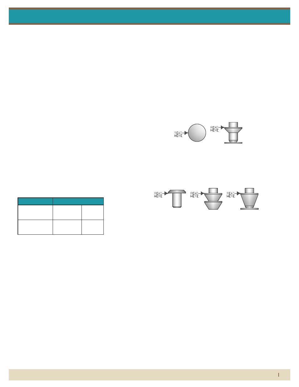
Float types and orientations
GV FLOAT
GS FLOAT
BL FLOAT
LJ FLOAT
HF FLOAT
Single Switch
Dual Switch
1 (+)
High Switch
1(+)
2(–)
2 (–)
Low Switch
4(+)
5(–)
Pressure and temperature ratings are based on a study of the engineering data for
particular materials used in construction and on the design of individual models.
This information is supplemented by destructive test results. Meters with stainless
enclosures must never be operated without shields securely in place. Meters
exposed to difficult environments such as those created by certain chemicals,
excessive vibration or other stress inducing factors could fail at or below the
suggested maximums. Never operate meters above pressure and temperature
maximums. It is strongly recommended that all meter installations utilize an
appropriate pressure relief valve and/or rupture disc. The pressure settings and
locations of these devices should be such that meters cannot be over pressurized.
Meter failure could result in damage to equipment and serious personal injury.
Always use suitable safety gear, including OSHA approved eye protection when
working around meters in service. We are happy to pass along chemical
compatibility information that has been published by the manufacturer's of raw
materials used in our products; however, this information should not be construed
as a recommendation made by King Instrument Company, Inc. for a specific
application.
Remove the shield from the frame by loosening the 4 shield screws with a
3
16
" hex
wrench. Loosen the scale plate screws and remove the scale plate. Loosen the
tube retainer screws and pull the tube retainer forward. Rotate the glass tube to
loosen the o-ring seal. Carefully push the glass tube up until its bottom clears the
inlet fitting. Angle the bottom of the glass tube down and away from the frame. Use
caution. Pulling the glass tube at an extreme angle, or by excessive force will
cause the tube to break. Do not allow the float to fall. Float damage may result in
meter inaccuracy.
Inspect all parts for damage prior to re-assembly. Replacement of o-rings during
meter maintenance is recommended. O-rings should be generously lubricated
using a silicone based o-ring lubricant. Insert the float and float stops into the glass
tube. Make sure the orientation of the float is correct prior to installing. Carefully
slide glass tube assembly onto top fitting at a slight angle and align with bottom
fitting. Secure the tube by pushing the tube retainer between the glass tube and the
upper fitting and tighten the screws. Replace the scale plate making sure the
referrence line on the scale is aligned with the reference line on the glass tube.
Re-install the front shield.
*Do not use cleaning agents that will damage float, tube or o-rings.
Meters should be cleaned with a mild soap solution. This will be an effective
cleaner of rust stains. Caution must be used so that materials of construction are
not damaged by cleaning solutions. Hard water deposits can be removed with 5%
acetic acid solution (vinegar).
Silver Series meters that require repair should be sent to the factory. Please call for
a Return Merchandise Authorization (RMA) number and return instructions.
-Serious property damage and great personal injury could occur as the result of a
meter misused or used in an unsuitable application.
CAUTION:
CLEANING:
REPAIR:
WARNING:
LATCHING REED SWITCH
All Silver Series flowmeters may be fitted with one or two latching reed switches.
The switch assembly is mounted on the scale plate. The switch can be positioned
to trip at any point on the scale.
The switch is a reed type and uses a biasing magnet to give it the latching feature.
The float contains hermetically sealed magnet(s), so when the float comes in
proximity to the switch it closes and remains closed (latched) when the float moves
below the switch it resets itself. Contact King Instrument Company for multiple
switch options.
LATCHING REED SWITCH-ELECTRICAL
SPECIFICATIONS
TYPE:
POWER:
SWITCHING VOLTAGE:
BREAKDOWN VOLTAGE:
SWITCHING CURRENT:
SPST
4W Max.
30V DC Max.
200V DC Min.
0.2A Max.
CARRY CURRENT:
1.4A Max.
INITIAL CONTACT RESISTANCE:
0.020 Ohm Max. @ 50% magnetic overdrive
SWITCH ISOLATOR OPTION:
Latching reed switches can be used as stand alone devices, or may be connected
to a switch isolator for intrinsically safe applications. The purpose of the switch
isolator is to supply electrical signals between safe and hazardous areas in either
direction while limiting the amount of energy that can be transferred even under
fault conditions. Switch isolators are available with 220VAC, 110VAC or 24VDC
supply voltage requirements, contain single pole double throw (SPDT) relays, and
are DIN rail mountable. See switch isolator specifications for electrical connections
and further details.
FLOAT TYPES AND
ORIENTATIONS:
1 (+)
High Switch
2 (-)
1 (+)
2 (-)
Low Switch
4 (+)
5 (-)
-Silver Series meters have o-ring seals. Use with incompatible fluids may cause
o-rings to swell which may cause glass tube to fail.
To minimize downtime, Silver Series metering tubes are designed to be removed
without uninstalling the flowmeter from the piping system. Meter should be drained
prior to maintenance.
GV FLOAT
Highest
immunity to
viscous fluids
with medium
meter capacity.
LJ FLOAT
Highest
immunity to
viscous fluids
with medium
meter capacity.
HF FLOAT
Highest
immunity to
viscous fluids
with medium
meter capacity.
BL FLOAT
Lowest meter
capacity or
medium capacity
with low
viscosity fluids
GS FLOAT
Maximum flow
meter capacity
with limited
viscosity
immunity
Silver Series