Poe+ desktop gigabit switch english, Connections & indicators, Placement – INTELLINET NETWORK 560856 8 Ports Gigabit PoE+ Desktop Ethernet Switch (4+4) User Manual
Page 2: 2english
2
ENGLISH
PoE+ Desktop Gigabit Switch
English
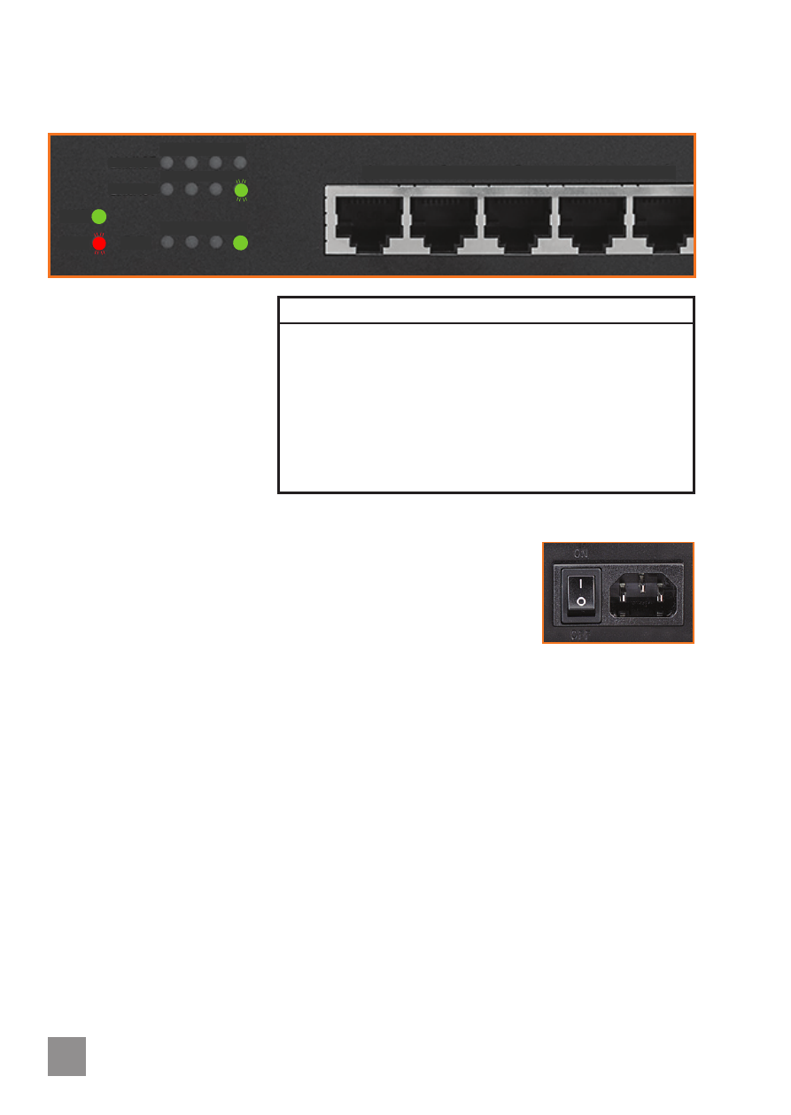
LED Status Operation
Power
On
Power on
Off
Check the AC connection; turn the power on
PoE
On
Port is linked to a PSE/PoE device
Off
No PSE/PoE device is linked
Link/Act
On
Valid port connection
Blinking
Valid port connection; data transmitted/received
Off
No link established
Loop
Blinking
A loop exists
Off
No loop
CONNECTIONS & INDICATORS
LEDs
The LED indicators make it
easier to monitor the switch
and its connections.
Ports
All ports on the switch support
Auto-MDI/MDI-X functionality,
so crossover cables and uplink
ports are not needed for
connections to PCs, routers,
other switches, etc. Cat5/5e/6 UTP/STP cables provide optimal performance; if a status LED
doesn’t indicate a link or activity, check the corresponding device for proper setup and
operation.
• Power consumption: 75 watts (maximum)
• If Ports 1-2 only: PoE / PoE+ (up to 31.5 watts per port)
• If Ports 1-4: PoE (up to 15.4 watts per port)
Power
Use the included power cord to connect the device (next to the On/Off switch on the rear
panel) to an AC outlet. Confirm that the power LED on the front panel is lit.
PLACEMENT
Prior to use, it is recommended that the switch be placed/positioned:
• on a level surface that can support the weight of the switch
• with a minimum of 25 mm (1”) of clearance on the top and sides for adequate ventilation
• away from sources of electrical noise: radios, transmitters, broadband amplifiers, etc.
• where it cannot be affected by excessive moisture
Rackmount
The switch includes brackets and screws for optional rack mounting.
1. Disconnect any cables from the switch.
2. Position a bracket over the mounting holes on one side of the switch and secure it in place
with screws.
3 Repeat Step 2 on the other side of the switch.
4. Position the switch in the rack and screw the brackets to the rack.
5. Reconnect any cables.
• The two holes on the bottom are for mounting on a wall.
Link/ACT
Link/ACT
Loop
PWR
PoE
1 2 3 4
1 2 3 4
5 6 7 8
1 2 3 4 5
ON
OFF
50/60 Hz
100-240 VAC