Connect the optional digital communication output, User interface and navigation, User interface – Hach-Lange POLYMETRON 9500 Basic User Manual User Manual
Page 19: Figure 10
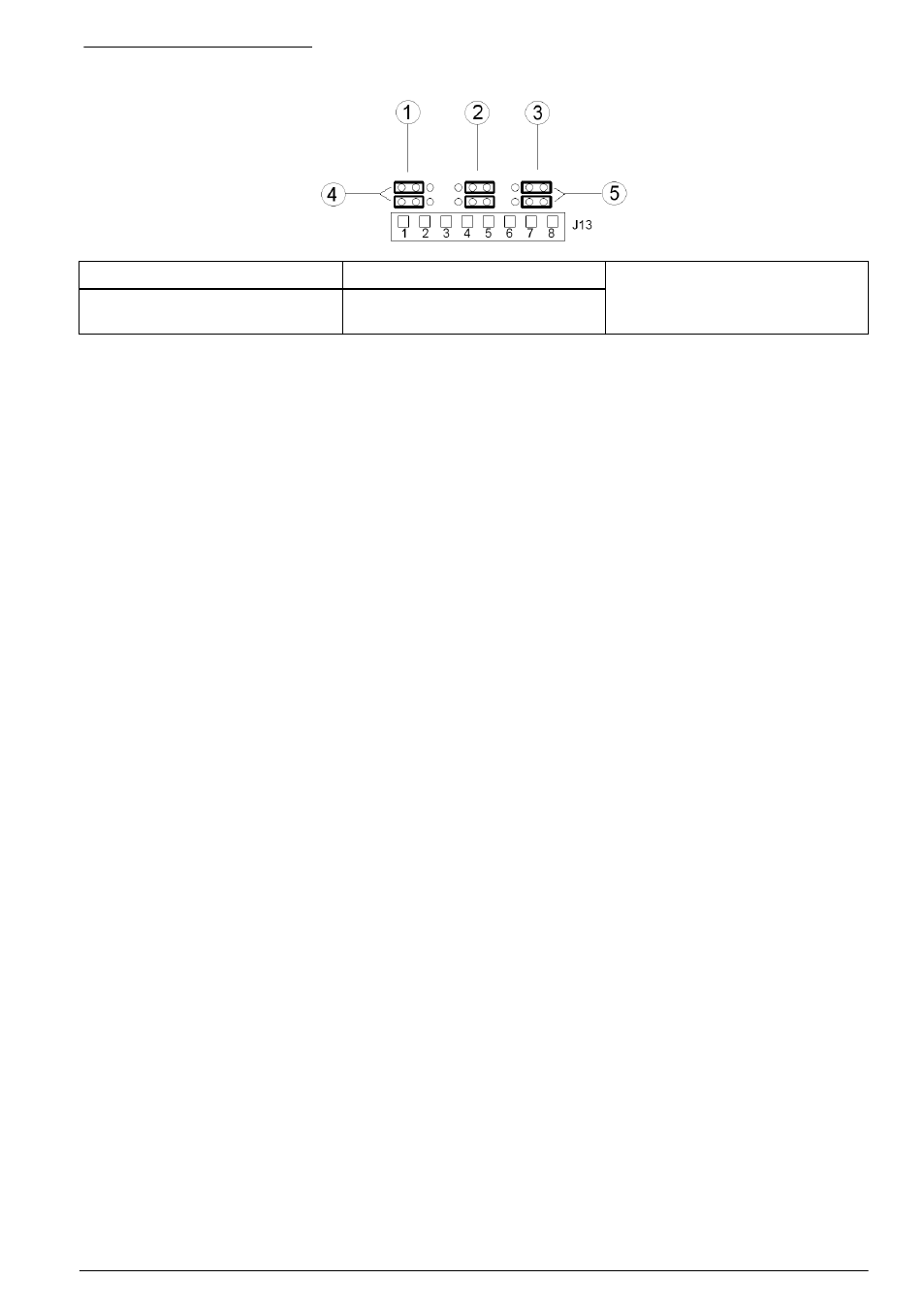
Figure 10 Jumper settings
1 Input 1 configuration jumpers
3 Input 3 configuration jumpers
5 Jumpers positioned to the right
for voltage inputs
2 Input 2 configuration jumpers
4 Jumpers positioned to the left for
switch inputs
1. Open the controller cover.
2. Feed the wires through the cable gland.
3. Adjust the wire as necessary and tighten the cable gland.
4. The jumpers are positioned immediately behind the connector. Remove the connector for
improved access to the jumpers and configure the jumper settings according to the type of input
as shown in
.
5. Close the controller cover and tighten the cover screws.
6. Configure inputs in the controller.
Note: In switch input mode the controller supplies 12 volts to the switch and is not isolated from the controller. In
voltage input mode the inputs are isolated from the controller (user input voltage from 0 to 30 volts).
Connect the optional digital communication output
The manufacturer supports Modbus RS485, Modbus RS232 and Profibus DPV1 communication
protocols. The optional digital output module is installed in the location indicated by item 4 in
on page 12. Refer to the manual supplied with the network module for more details.
For information about Modbus registers, refer to
User interface and navigation
User interface
The keypad has four menu keys and four directional keys as shown in
.
English 19