English, Ab a b – CAME BX-P Kit User Manual
Page 16
16
A
ll t
h
e d
at
a a
n
d i
n
fo
rm
at
io
n c
o
n
ta
in
ed h
er
ei
n
i
s c
o
n
si
d
er
ed
s
u
b
je
ct to c
h
an
g
e a
t a
n
y t
im
e a
n
d a
t o
u
r d
is
cr
et
io
n
ENGLISH
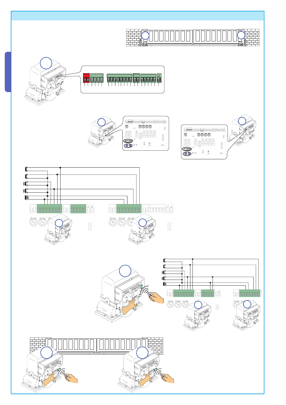
2) Perform the electric connections on motor
A’s control board as instructed in paragraph
6.3 electric connections, page 9.
5
6
7 %
,
.
0
# #
%" %"
&! &#
&
" "
A
1) Coordinate ratiomotor A and B’s movement direc-
tion, changing the rotation of motor B (see paragraph
6.4 ratiomotor/end-stop connection).
A
B
9 Connection of two paired ratiomotors with a single control
0
# #
0
# #
&! &#
&
" "
#
#
0
A
A
B
A
B
,).%
/.
!&
!&
#(
#(
!&
,).%
/.
!&
!&
#(
#(
!&
0
# #
0
# #
&! &#
&
" "
#
#
0
A
B
A
B
4) Perform the connections between the two
control boards as shown in the fi gure.
Note: the partial opening key (2-3P) should be
connected to the control board terminal board
of the relevant motor (motor A
for opening toward the left, B for
opening toward the right).
5) Insert the AF1 radio card on ratiomo-
tor A’s control board and proceed with
the installation of the remote control,
use CH2 channel (command for two
paired motors, see chapter 7, pg.12).
After saving the code on CH2, connect
B1 and B2 contacts to 2 and 7 contacts.
Select the type of command on both
boards (see dip-switch 2 and 3).
3) Perform the same settings and
functions (dip-switch) on both
boards.
6) For the automation’s release system
on both motors, insert an AF2 radio
card on motor A’s control board and
one on motor B’s and carry out the pra-
tico system installation procedure (see
chapter 8, pg.16) on both boards.