Installation instructions cont’d – Hydrotech ProFlo SXT Valve Downflow_Upflow Automatic Water Softeners Operation Manual User Manual
Page 6
4
Installation Instructions Cont’d
2.
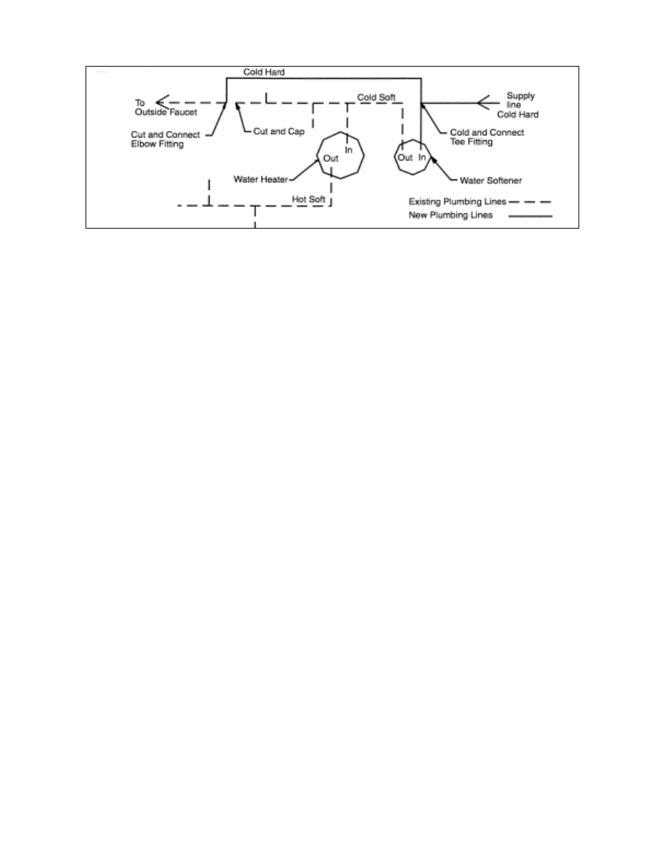
Outside faucets used to water lawns and gardens should not supply softened water. A new water line is often
required to be connected to supply hard water to the inlet of the water softener and to the outside faucets. Cut the
water line between where it enters the house and before any lines that branch off to feed the hot water heater or
other fixtures in the house and as near the desired location of the water softener as possible. Install a tee fitting on
the feed end of the cut pipe, and an elbow fitting on the other end. Install piping from the tee to the inlet of the water
softener and from the elbow to the outlet of the softener. To sever the water lines which branch off to feed any
outside faucets, cut the branch lines approximately two inches from the fitting on the main water line. Install an
elbow on the end of the pipe nearest the outside faucet and a cap on the end connected to the existing water line.
Install piping from the tee installed on the inlet line to the water softener to the elbow installed on the pipe to the
outside faucet. Following this procedure will result in all lines in the house, with the exception of the outside faucets,
but including the water heater and therefore the hot water lines, being supplied with soft water.
3.
Familiarize yourself with the location of the inlet, outlet and drain on the control valve. Be very careful not to get the
controls wet.
4.
Attach the bypass valve to the control valve. Connect the inlet and outlet of the water softener to the plumbing in the
house. The control valve must not be submitted to temperatures above 71°C (110°F). When sweat fittings are used,
to avoid damaging the control valve, solder the threaded copper adapters to the copper pipe and then, using Teflon
tape, screw the assembly into the bypass valve.
CAUTION - do not use pipe thread compound as it may attack the material in the valve body.
5.
Using teflon tape, screw the 1/2" hose barb into the drain port in the valve. Attach 1/2" drain hose to the hose barb
and tighten securely with a hose clamp. Run the drain line to a floor drain or a laundry drain. Complete any
necessary plumbing.
6.
On twin tank units, pull the 3/8" brine line through the hole in the back of the brine tank. Connect the brine line to the
fitting on the side of the valve using the nut and ferrule. Tighten snugly.
7.
Make sure the bypass valve is in the service position.
8A. Upflow Programming
i. Plug the 24-volt transformer into a 120 VAC 60 Hz outlet. This valve has four positions: 1) Brine / slow rinse 2)
Backwash 3) Rapid Rinse and 4) Brine Refill. When the valve is in the Service position, the extra cycle button (far
left button as shown on Figure 4A) must be pressed and held for 5 seconds to advance the valve into Position 1 -
Brine / slow rinse (1...59). Press the extra cycle button again to advance the valve into Position 2 - Backwash
(2...9). Slowly turn on the water supply and allow the unit to backwash until the air purges out of the tank and
clears the system.
ii. Press the extra cycle button once more to advance to Position 3 - Rapid Rinse. Press once more to advance to
Position 4 - Brine Fill and allow the brine tank to fill until there is 6" of water in the brine tank.
iii. Press the extra cycle button to advance the valve to the Service position. Press and hold manual cycle button
again for 5 seconds to advance the valve to Position 1 - Brine / slow rinse. Verify that there is brine being drawn
from the brine tank. If not repeat steps 9 through 10 or see Cleaning the Injector Assembly on page 6 of this
manual.
iv. Press the extra cycle button to advance the valve to Position 2 - Backwash and then press the extra cycle button
once more to advance to Position 3 - Rapid Rinse. Press the extra cycle button again to advance the valve to
Position 4 - Brine fill. Allow the valve to fill until there is at least 6" of water in the tank. Additional water can be
added manually at this time to achieve this level, however, the valve needs to be in the brine fill position to allow
all air to be purged from the pressure regulator and injector set.
Figure 3